
System for aperturing and coaperturing webs and web assemblies

a web and web assembly technology, applied in the field of system for aperturing and coaperturing webs and web assemblies, can solve the problems of shear of the web near the tip of the pin, a number of challenges for high-speed manufacturing, etc., and achieve the effect of reducing the amount of material dragging, reducing the in-plane deformation of the web, and reducing the frictional for

Inactive Publication Date: 2005-01-04
KIMBERLY-CLARK WORLDWIDE INC
View PDF76 Cites 84 Cited by
  • Summary
  • Abstract
  • Description
  • Claims
  • Application Information

AI Technical Summary

Benefits of technology

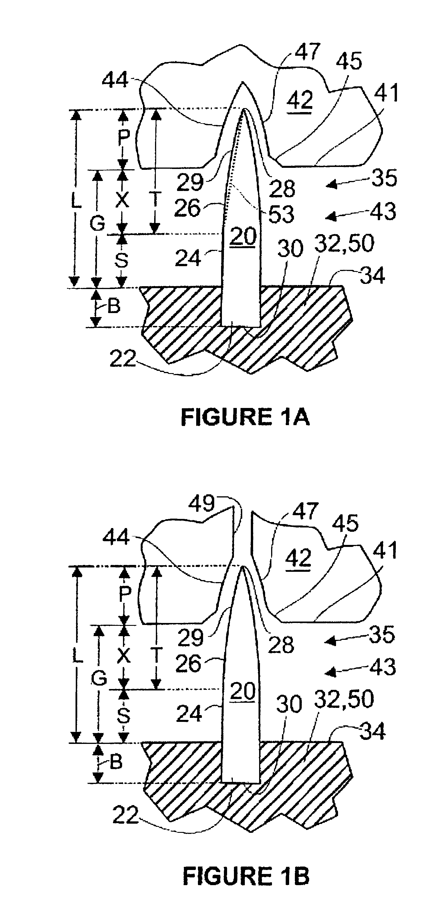
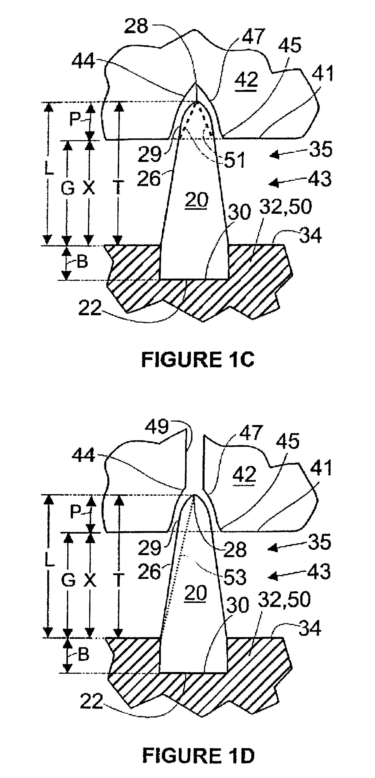
It has been discovered that decreased in-plane deformation of a web (including a composite web assembly) by aperturing pins can be achieved during aperturing if the pins are provided with a tapered section of sufficient length to reduce frictional forces between the pins and the web in the aperturing nip to reduce the amount of material dragged by the pins into the receiving recesses of the female roll, and to reduce friction between the pins and the web as the pins are withdrawn from the web. Achieving this objective is possible when the characteristic pin has a tapered section that not only extends into the receiving recess of the female roll, but also occupies a substantial portion of the gap between the pin roll and the female roll (i.e., between the support surface of the pin roll and the perimeter of the female roll) at mid-nip, such as at least about 10% of the gap, specifically at least about 30%, more specifically at least about 50%, more specifically still at least about 70%, and most specifically substantially all of the gap at mid-nip. The extended tapered section of the pin can reduce friction between the pin and the web as a substantial portion of the web remains in contact with the tapered portion as it is apertured. In one embodiment, the tapered section of the pin extending between the perimeter of the female roll at mid nip toward the pin roll is at least 30% as long as or longer than the thickness of the web in the aperturing nip, and more specifically at least 50% as long as the thickness of the web at mid-nip.
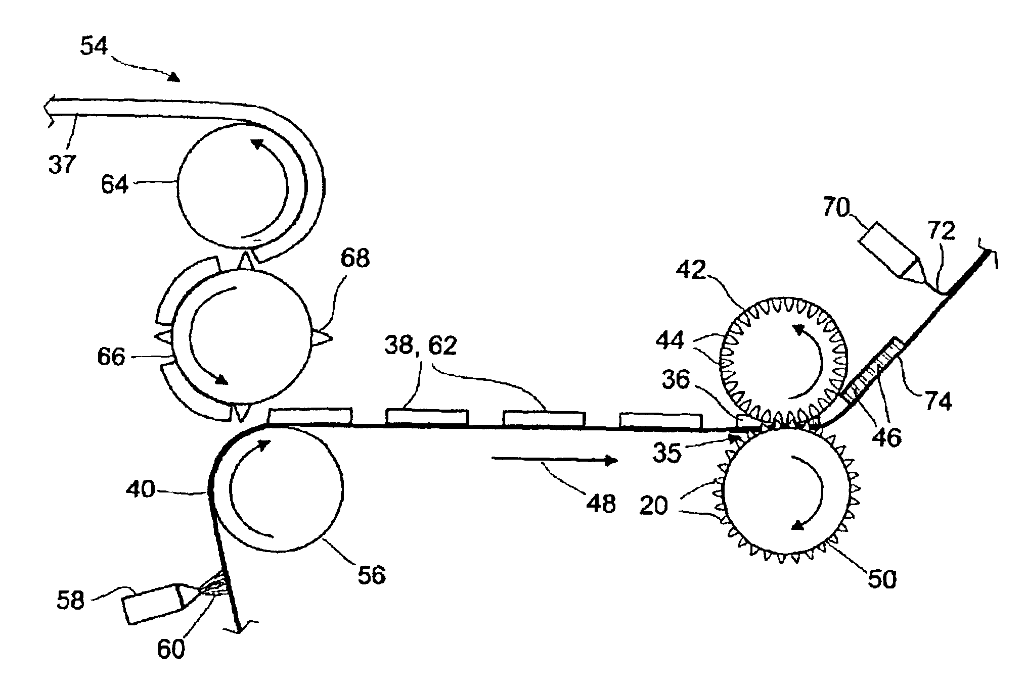
In a useful process employing the highly tapered pins of the present invention, a composite web is formed by cutting absorbent sections from a web of fluff pulp (also known as airfelt) comprising a mat of comminuted wood pulp fibers, and placing the absorbent sections on a carrier layer that can be a porous nonwoven web such as a spunbond web that may serve as a cover layer in the completed absorbent article. Adhesive is placed on portions of the carrier layer to restrain the absorbent sections on the nonwoven web. The composite web assembly comprising absorbent sections on the carrier layer then enters an aperturing nip where tapered pins on a pin roll first contact the carrier layer and then puncture the carrier layer and the absorbent sections, thereby coaperturing the composite web assembly. The tapered section of the pins at mid-nip can extend from the tip of the pin in the receiving recess of the female roll into the gap between the female roll and pin roll, thereby reducing friction between the web and the pin during withdrawal of the pin from the web. A convexly tapered section of the pin coupled with a receiving recess having a concavely tapered portion can result in high definition of the apertured portion of the web.
In one embodiment, the stability of the web during aperturing is enhanced by providing a deformable restraint layer on the pin roll, such as a layer of a deformable foam material having holes to receive the pins. The deformable restraint layer on the pin roll can engage the web in the aperturing nip and reduce in-plane dislocation. The deformable layer can initially cover the pins or allow them to protrude only a short distance from the deformable layer, but in the nip as the deformable restraint layer presses against the web, the restraint layer can become compressed, causing it to recede and allowing the pins to emerge more fully to aperture the web. In this manner the web is restrained in the nip, reducing its tendency to shear or deform in the plane and reducing the tendency of the web to follow the pins as they enter into the receiving recesses of the female roll, leading to sharper aperture definition and improved runnability.

Problems solved by technology

Aperturing and coaperturing can be desirable for many products, but they pose a number of challenges for high-speed manufacturing.
Challenges arise in many cases due to in-plane deformation of the web or web assembly as it passes through an aperturing nip.
As a pin first engages the web, the tip of the pin travels at a higher radial velocity than the perimeter of the opposing female roll, resulting in shear of the web near the tip of the pin.
The shear or dislocation experienced by portions of the web near the resulting apertures can reduce the clarity of the aperture.
When the web has been previously embossed or otherwise textured, the clarity of the embossment or texture can suffer because of in-plane dislocation and shear of the web.
Particularly severe challenges are encountered in coaperturing web assemblies comprising two or more layers such as a high-bulk absorbent web of fluff disposed on a denser or substantially thinner nonwoven web or film.
The dissimilar physical properties of the two or more layers can result in complex in-plane stresses and a variety of aperture defects or web deformation problems.
Designs for aperturing pins usually seek to minimize pin length because longer pins create a higher level of differential movement in the aperturing nip, cause more in-plane dislocation of the web, and are more likely to become jammed in the receiving recesses of the female roll.
Nevertheless, conventional pin designs result in a variety of problems with aperture quality.
It is believed that one problem with prior pin design has been the abbreviated length of the tapered section, which is often tapered at a high angle relative to the vertical axis, such as a 45 degree angle.
The short span of the tapered section tends to result in greater web disruption and densification of the web near the aperture.

Method used


Image

  • System for aperturing and coaperturing webs and web assemblies
  • System for aperturing and coaperturing webs and web assemblies
  • System for aperturing and coaperturing webs and web assemblies

Examples


Embodiment Construction

FIGS. 1A-1D depict several embodiments in cross-sectional view of a pin 20 retained in a support 32 (e.g., a pin roll 50 or mounting plate) having a support surface 34. The pin 20 has a base 22, a shaft 24 rising above the support surface 34 of the support 32, a tapered section 26, and a tip 28 at the upper end of the tapered section 26. Distal to the tip 28 is the base end 30. The shaft 24 typically has a substantially uniform width, followed by the tapered section 26 whose width generally decreases with distance from the base end 30. In the tapered section 26, wherein the relationship between width and distance from the base end 30 is not linear in several embodiments. The sides of the tapered section 26 can be convex (as shown), concave, or a combination thereof, though in some embodiments a concave taper is particularly useful. The relationship between width and distance from the base end 30 is generally monotonic in preferred embodiments, but a short excursion from a monotonic ...


PUM

PropertyMeasurementUnit
diameteraaaaaaaaaa
taper lengthaaaaaaaaaa
densityaaaaaaaaaa

Abstract

Improved aperturing of a web can be obtained by providing pins with an extended tapered section that is substantially convex in shape. When the tapered section is longer than the penetration depth of the pins into the receiving recesses of a female roll, frictional forces in the nip between layers are reduced. Pins with extended tapered sections can be used in devices for producing apertured composite web assemblies comprising sections of absorbent matter attached to a nonwoven web or other carrier layer.

Description

BACKGROUNDIn the production of disposable absorbent articles, pin aperturing is a widely used and inexpensive method for providing apertures in a web for purposes such as enhancing fluid transport, increasing void space, or improving the appearance of a product. Both single webs and composite webs can be pin apertured in an aperturing nip comprising a pin roll and a female roll. When an assembly of two or more layers are apertured simultaneously, the assembly is said to be coapertured. Aperturing and coaperturing can be desirable for many products, but they pose a number of challenges for high-speed manufacturing. Challenges arise in many cases due to in-plane deformation of the web or web assembly as it passes through an aperturing nip. As a pin first engages the web, the tip of the pin travels at a higher radial velocity than the perimeter of the opposing female roll, resulting in shear of the web near the tip of the pin. As the pin pushes the web down into the receiving recess of...

Claims


Application Information

Patent Timeline
Patent Type & Authority Patents(United States)
IPC IPC(8): A61F13/15B26F1/00B26F1/24
CPCA61F13/15707B26F1/24Y10T156/1304Y10T156/133Y10T156/1077Y10T156/1056Y10T83/0481Y10T83/7809Y10T83/9314
Inventor COWELL, CHRISTINE M.KUBALEK, RICHARD W.LAKE, ANDREW M.LINDSAY, JEFFREY D.MODER, SUSAN J.RASMUSSEN, SHELLEY R.WALKER, LAURA J.
Owner KIMBERLY-CLARK WORLDWIDE INC
Learn More