Method and system for dynamically operating memory in a power-saving error correcting mode

a technology of dynamic operation and power saving, applied in the field of memory devices, can solve the problems of data errors generated and the second rate may be sufficiently low, and achieve the effects of preventing any data errors from being generated, low scrubbing rate, and low ra

Inactive Publication Date: 2005-01-04
MICRON TECH INC
View PDF59 Cites 93 Cited by
  • Summary
  • Abstract
  • Description
  • Claims
  • Application Information

AI Technical Summary

Benefits of technology

A method and system for storing data in a dynamic random access memory (“DRAM”) device in either a normal operating mode when the DRAM device is active or a power-saving mode when the DRAM device is inactive. In the normal operating mode, data may be read from or written to the DRAM device, and memory cells in the DRAM device are refreshed at a first rate that is sufficiently high to prevent any data errors from being generated. In the power-saving mode, the memory ce

Problems solved by technology

The second rate may be sufficiently low that data errors are generated, but error correcti

Method used


Image

  • Method and system for dynamically operating memory in a power-saving error correcting mode
  • Method and system for dynamically operating memory in a power-saving error correcting mode
  • Method and system for dynamically operating memory in a power-saving error correcting mode

Examples


Embodiment Construction

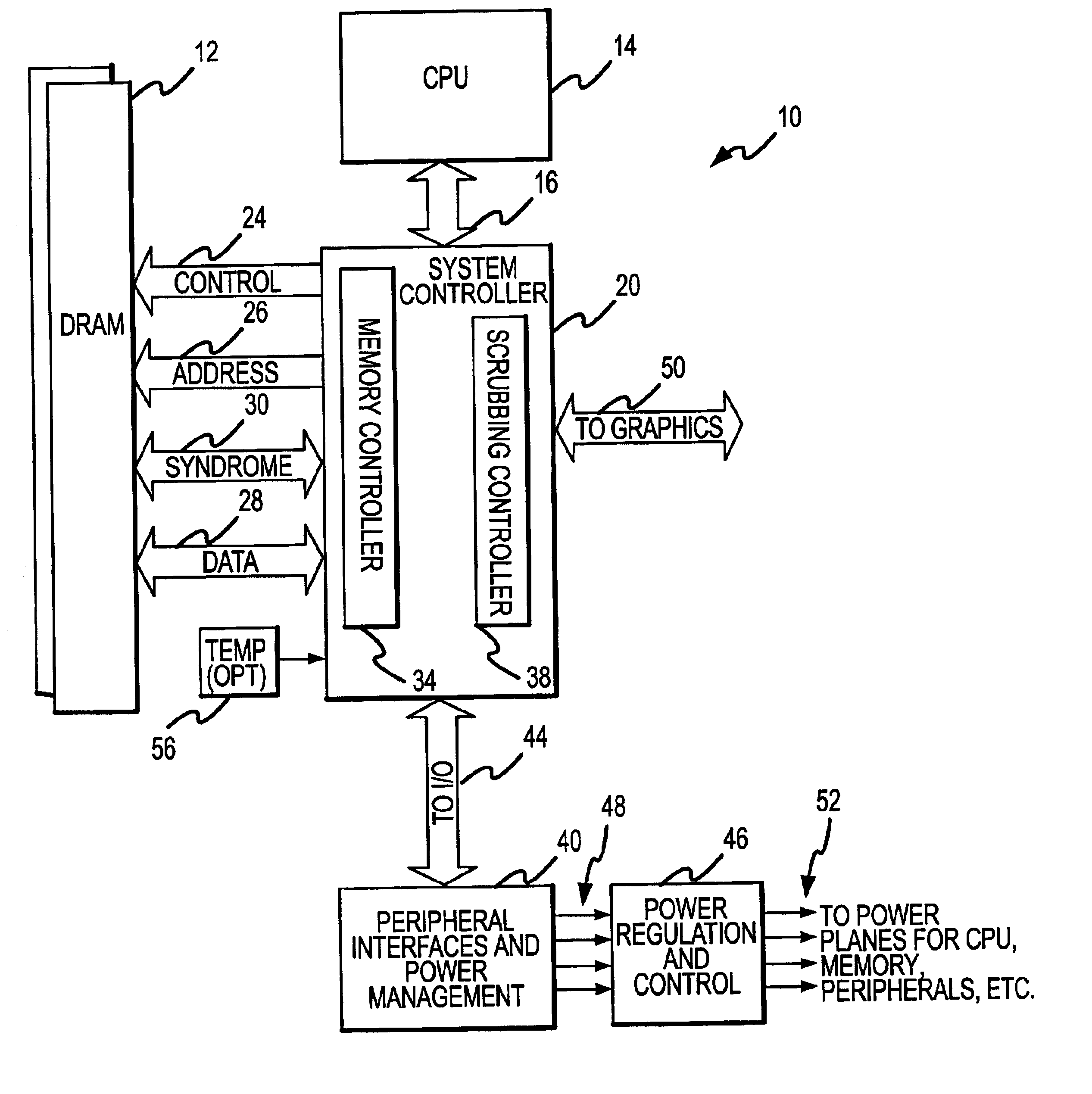
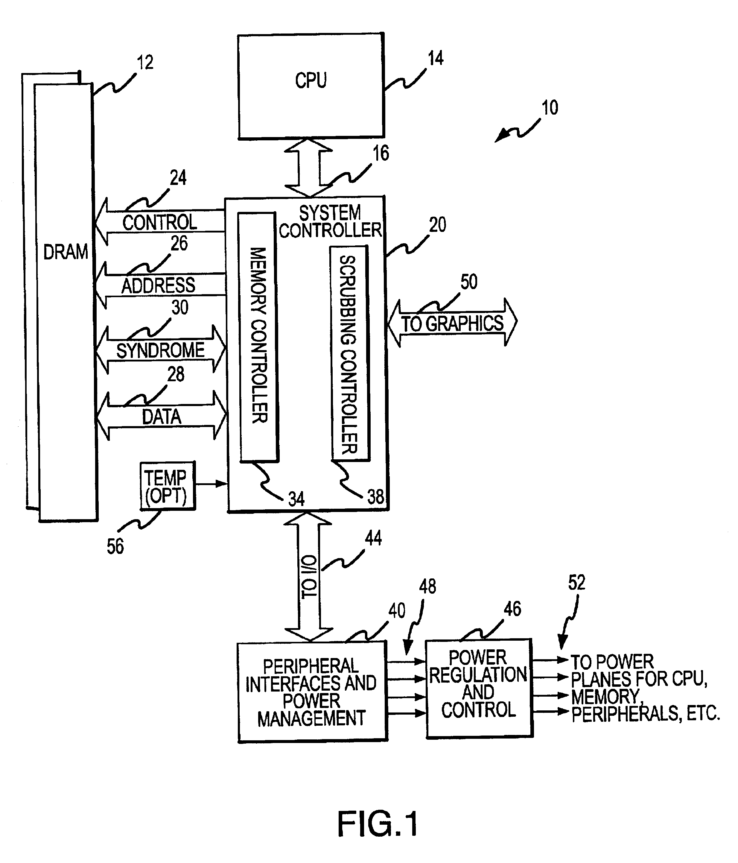
One embodiment of a computer system 10 containing a DRAM device 12 that uses relatively little refresh power in at least some operating modes is shown in FIG. 1. The computer system 10 includes a central processing unit (“CPU”) 14 for performing various computing functions, such as executing software to perform specific calculations or tasks. The CPU 14 includes a processor bus 16 that normally includes an address bus, a control bus, and a data bus. The CPU 14 is also coupled through a system controller 20 to system memory implemented using the DRAM device 12. The system controller 20 includes a control bus 24, an address bus 26 and a data bus 28, all of which are coupled to the DRAM device 12 in a conventional manner. However, the system controller 20 also includes an additional data bus, which will be referred to as a check bit bus 30. The system controller 20 also includes a memory controller 34 for controlling the operation of the DRAM device 12 and a scrubbing controller 38, th...


PUM


Abstract

A scrubbing controller used with a DRAM stores data in an error correcting code format. The system then uses a memory control state machine and associated timer to periodically cause the DRAM to read the error correcting codes. An ECC generator/checker in the scrubbing controller then detects any errors in the read error correcting codes, and generates corrected error correcting codes that are written to the DRAM. This scrubbing procedure, by reading error correcting codes from the DRAM, inherently refreshes memory cells in the DRAM. The error correcting codes are read at rate that may allow data errors to be generated, but these errors are corrected in the memory scrubbing procedure. However, the low rate at which the error correcting codes are read results in a substantial power saving compared to refreshing the memory cells at a higher rate needed to ensure that no data errors are generated.

Description

TECHNICAL FIELDThe invention relates to memory devices, and, more particularly, to a method and system for allowing a memory to operate in a manner that corrects data errors that may be generated by operating the memory in a mode that consumes relatively little power.BACKGROUND OF THE INVENTIONSubstantially all modern computers and other digital systems rely on semiconductor memory devices to store data and instructions for processing by a central processing unit (CPU). Most of these systems have a system memory, which usually consists of dynamic random access memory (“DRAM”) devices. The memory storage cost / bit of DRAM devices is relatively low because a DRAM memory cell needs relatively few circuit components to store a data bit as compared with other types of memory cells, such as static random access memory (“SRAM”) devices. Thus, a high capacity system memory can be implemented using DRAM devices for a relatively low cost.Although DRAM devices have the advantage of providing re...

Claims


Application Information

Patent Timeline
IPC IPC(8): G06F1/32G11C11/407G11C11/4076G11C11/406
CPCG06F1/3225G06F1/3275G06F11/106G11C11/4076G11C11/406Y02B60/1228G11C2207/2227Y02B60/1225Y02D10/00
Inventor KLEIN, DEAN A.
Owner MICRON TECH INC
Why Eureka
Try Eureka