System for excitation leadless miniature marker

Inactive Publication Date: 2005-01-04
VARIAN MEDICAL SYSTEMS +1
View PDF109 Cites 155 Cited by
  • Summary
  • Abstract
  • Description
  • Claims
  • Application Information

AI Technical Summary

Benefits of technology

Under one aspect of the invention, a system is provided for generating a magnetic field for excitation of a leadless marker assembly. The system includes a source generator assembly having a power supply, an energy storage device, a switching network and an untuned source coil interconnected and configured to deliver a selected magnetic excitation signal waveform, such as continuous bipolar or unipolar waveform, or a pulsed waveform. In one embodiment, the waveform can be configured to contain sufficient energy at the selected leadless marker resonant frequency to energize the marker sufficiently above the ambient environment background noise. Also, the waveform can be programmable in both pulse frequency and pulse duration. For example, the frequency may be programmed to be a single repetition frequency or a composite of two or more repetition frequencies. The duration can be programmed from a continuous wave (CW) waveform of repetitive pulses essentially continuous in nature to a single pulse burst of

Problems solved by technology

The process of distinguishing a weak marker signal from the strong continuous excitation signal, while maintaining sufficient accuracy and repeatability for determining the marker's location, has proven to be very difficult.
The required levels of magnetic excitation for the markers in the above patents are relatively low such that the excitation energy in the source coil is substantially consumed after each pulse due to the pulse circuitry resistive losses.
The amplitude of the pulsed excitation signal required for these applications is relatively low since either the resonator circuit to be located is of a large size, the volume in which the resonator must be located is relatively small, or the accuracy requirements locating the resonator are quite low.
Accordingly, the existing systems are not suitable for use in many situations wherein highly accurate de

Method used


Image

  • System for excitation leadless miniature marker
  • System for excitation leadless miniature marker
  • System for excitation leadless miniature marker

Examples


Embodiment Construction

In the following description, certain specific details are set forth in order to provide a thorough understanding of various embodiments of the invention. However, one skilled in the art will understand that the invention may be practiced without these details. In other instances, well-known structures associated with magnetic excitation systems, resonating markers, and activators have not been shown or described in detail to avoid unnecessarily obscuring the description of the embodiments of the invention.

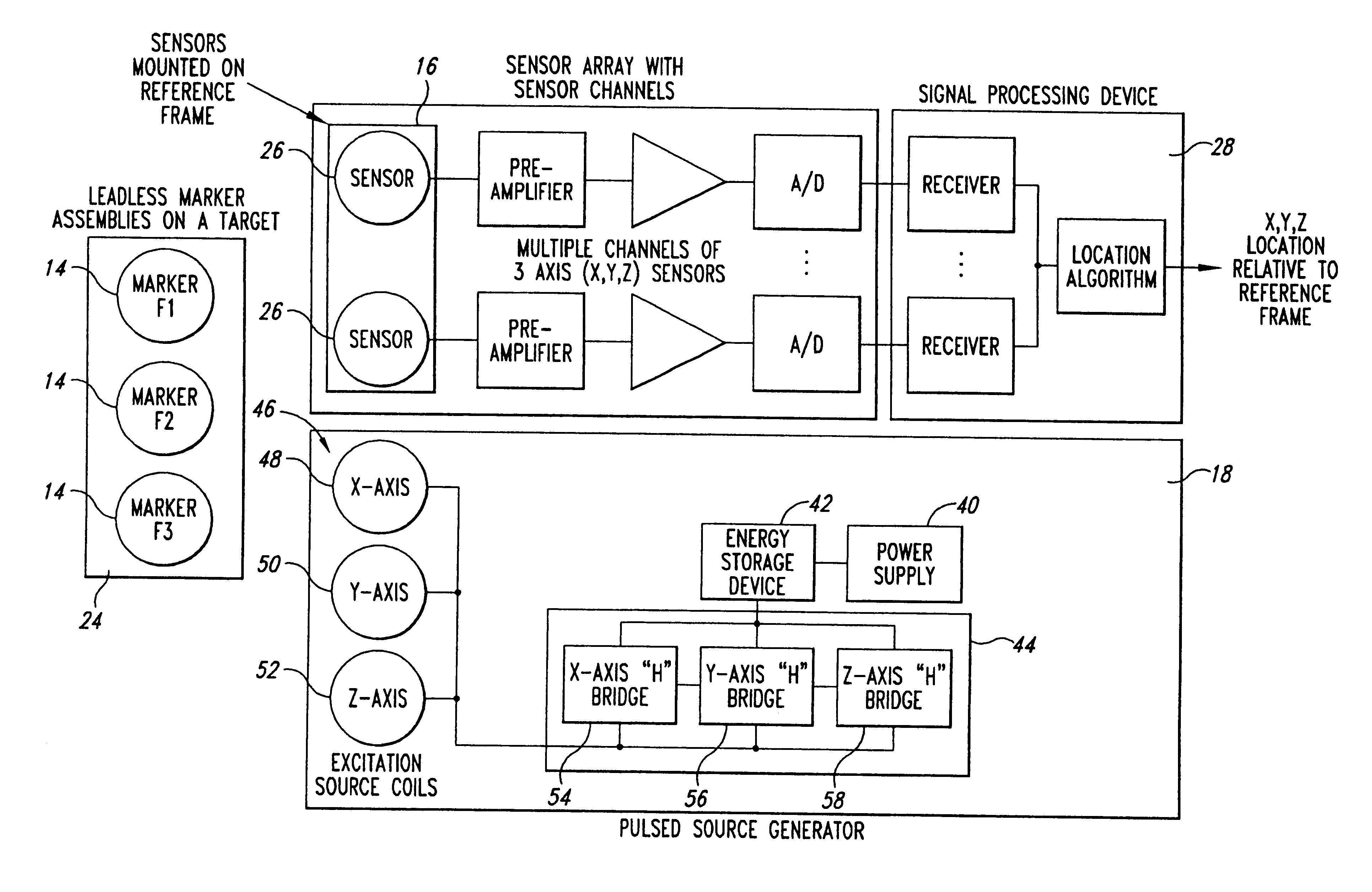
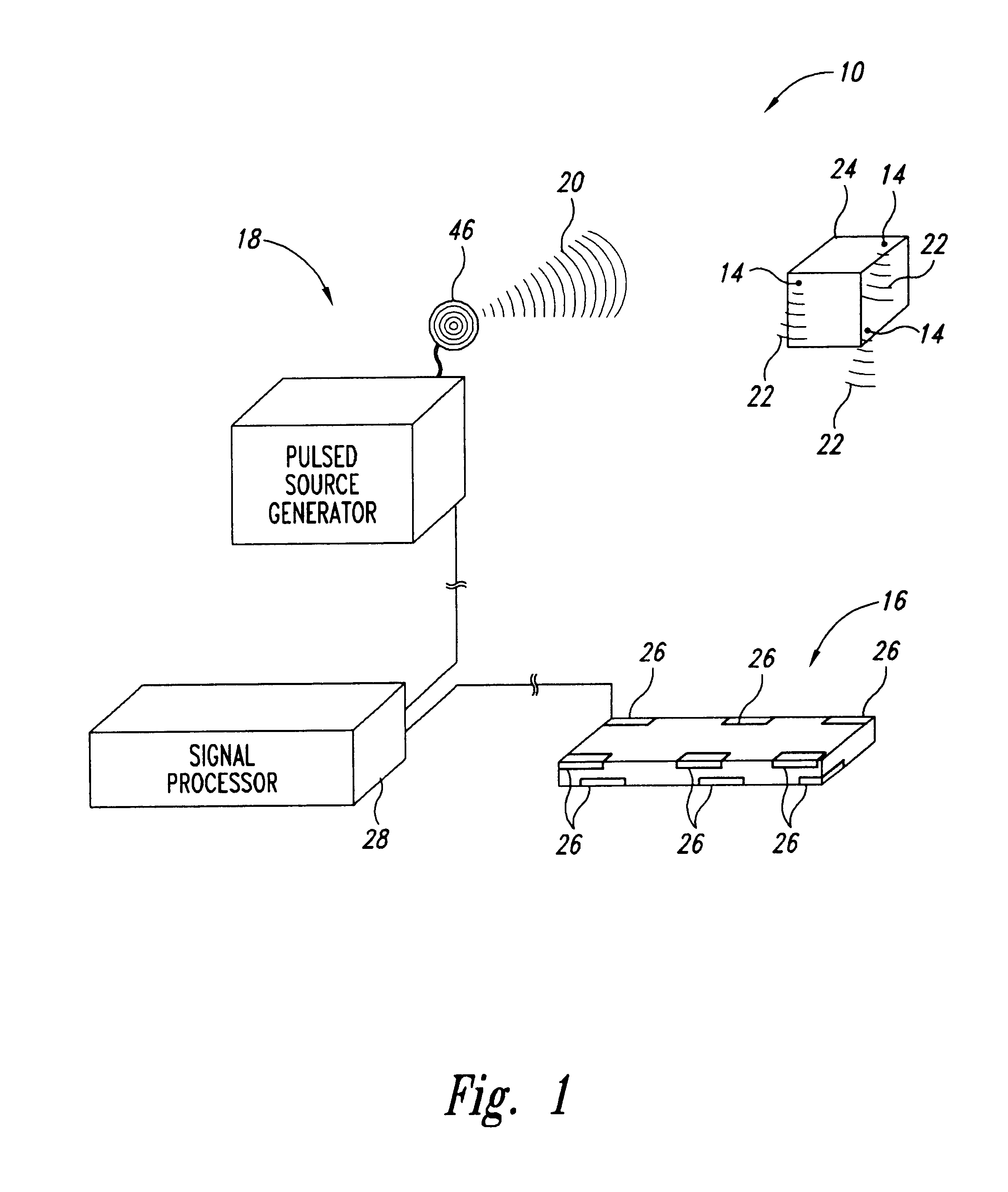
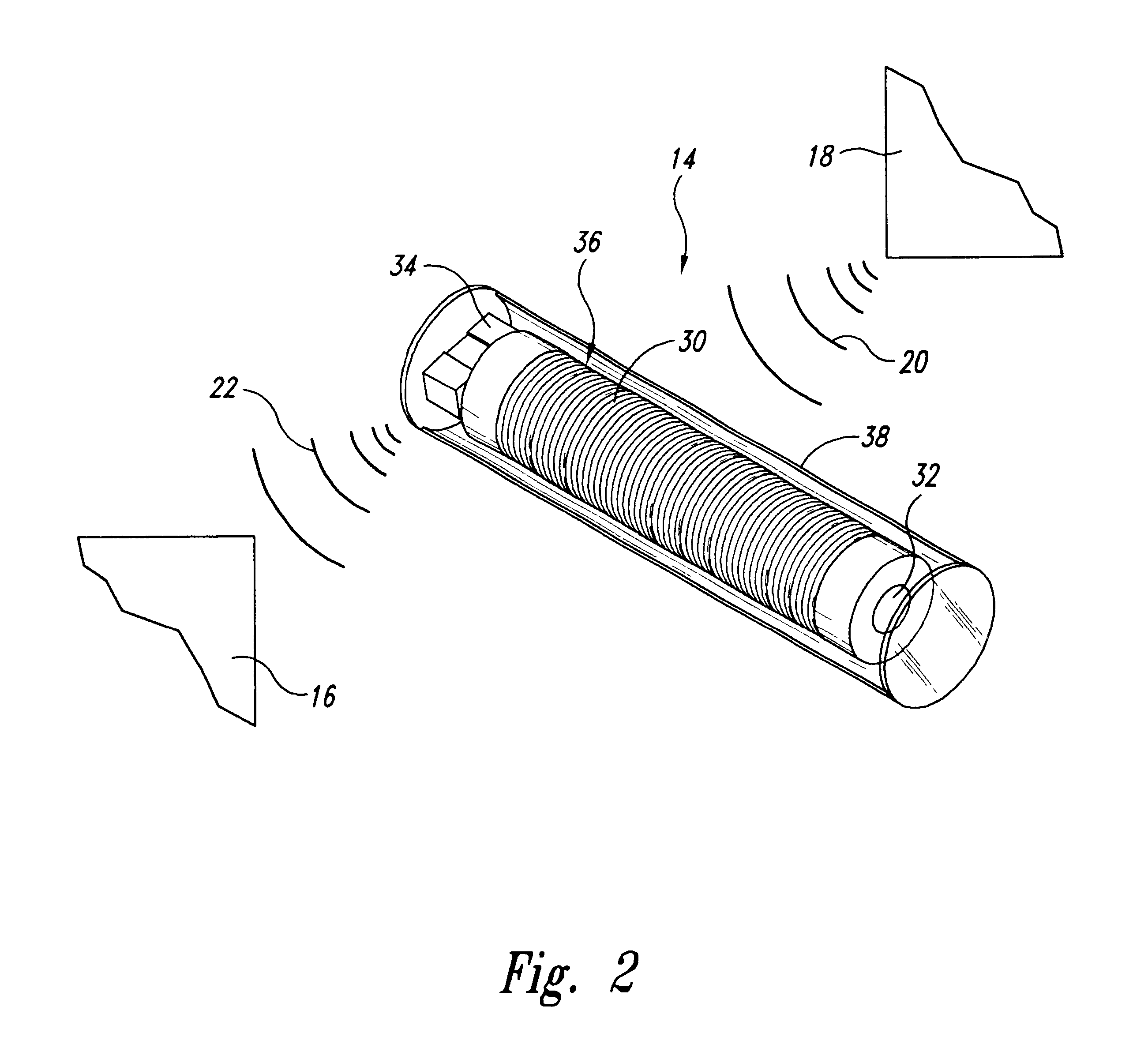
FIGS. 1-9 illustrate a system and components for generating an excitation signal for activating a resonating marker assembly and locating the marker in three-dimensional space in accordance with embodiments of the present invention. Several of the components described below with reference to FIGS. 1-9 can also be used in systems for performing methods in accordance with aspects of the present invention. Therefore, like reference numbers refer to like components and features throug...


PUM


Abstract

A system for generating an excitation field for excitation of a leadless marker assembly. One aspect of the system comprises a source generator assembly having a power supply, an energy storage device, a switching network and a source coil interconnected and configured to deliver a magnetic excitation signal waveform. The power supply is configured to deliver power to energize the energy storage device. The switching network is configured to: direct electrical current through the source coil; alternately switch between a first on position and a second on position; alternately transfer stored energy from the energy storage device to the source coil and to transfer stored energy from the source coil back to the energy storage device; and the source coil being coupled to the switching network to generate an excitation signal.

Description

TECHNICAL FIELDThis invention relates to systems for activating miniature markers, and more particularly to systems for excitation of resonating miniature marker assemblies for use in locating the markers in three-dimensional space.BACKGROUND OF THE INVENTIONSystems have been developed to activate and detect remote activatable marker assemblies positioned, as an example, in or on a selected item or object. The markers generate a signal used to detect the presence of the marker. Many of the activatable markers are hard-wired to a power source or other equipment external from the object. Other systems have been developed that utilize resonating leadless markers, also referred to as wireless active markers, positionable at or near a selected target. These wireless active markers are typically activated or energized by a remote excitation source that generates a strong continuous excitation signal. Accordingly, the markers generate a detectable marker signal that must be distinguished f...

Claims


Application Information

Patent Timeline
IPC IPC(8): A61B19/00A61N5/10G01B7/00G01S5/16
CPCA61B19/52A61B19/5244A61B2017/00411A61N2005/1051A61B2019/5458A61B2019/5475A61N5/1049A61B2019/5251A61B90/36A61B2090/3975A61B34/20A61B2034/2051A61B2090/3958
Inventor DIMMER, STEVEN C.
Owner VARIAN MEDICAL SYSTEMS
Why Eureka
Try Eureka