Switching power supply circuit

a power supply circuit and power supply circuit technology, applied in the direction of electric variable regulation, process and machine control, instruments, etc., can solve the problems of power factor drop, power factor drop, and power factor drop, so as to improve the conduction angle of alternating-current input current, improve the power factor, and improve the effect of rectification

Inactive Publication Date: 2005-01-04
SONY CORP
View PDF8 Cites 21 Cited by
  • Summary
  • Abstract
  • Description
  • Claims
  • Application Information

AI Technical Summary

Benefits of technology

As another alternative, the switching power supply circuit may be configured such that the power factor improving rectification means includes a transformer including a primary winding which serves as the first inductance and a secondary winding which services as a second inductance and a capacitor connected in parallel to the primary winding of the transformer to form a parallel circuit, the clamp capacitor of the active clamp means being connected to a node between one of the high speed recovery type diodes and the parallel circuit, the high speed recovery type diodes switching the rectification current on and off based on the voltage obtained by the voltage generation means to improve the power factor.
With the power supply circuits called a switching frequency control composite resonance type converter, a voltage based on a switching output voltage (voltage resonance pulse voltage) generated in the primary side voltage resonance converter (primary-side resonance circuit) is fed back to the smoothing capacitor through the power factor improving means or the power factor improving rectification means to increase the conduction angle of the alternating-current input current thereby to improve the power factor.
In this instance, the voltage resonance pulse voltage clamped by the active clamp means formed on the primary side is fed back to the power factor improving means or the power factor improving rectification means. Consequently, the switching control range is increased and a stabilized power factor characteristic can be achieved.
Or else, the voltage fed back to the power factor improving means or the power factor improving rectification means based on the voltage resonance pulse voltage is a pulse voltage generated in the active clamp means formed on the primary side. Consequently, the switching control range is increased and a stabilized power factor characteristic can be achieved.
Further, the power factor improving means or the power factor improving rectification means can eliminate the necessity for a series resonance capacitor.

Problems solved by technology

The circuit arrangement, however, has the following problems.
Therefore, a power supply circuit of an improved power factor ready for worldwide use cannot be achieved.
Further, the circuit described above exhibits a great drop of the power factor as the load power decreases and does not make a power supply of a stabilized improved power factor which operates suitably in response to a variation of the load.
In the case described above, however, since the current which should discharge the parallel resonance capacitor Cr through the inductances L1 and L2 is weakened with the current to be supplied from the tertiary winding N3 to the primary winding N1, the parallel resonance capacitor Cr cannot be discharged fully, which disables the ZVS operation.
Consequently, when the switching element Q1 is switched on, switching loss is generated and drops the efficiency.
This, however, provides restriction to the value of the inductance Ls of the power factor improving circuit 20 and the electrostatic capacitance value of the series resonant capacitor C10 and makes optimum designing difficult.

Method used


Image

  • Switching power supply circuit
  • Switching power supply circuit
  • Switching power supply circuit

Examples


first embodiment

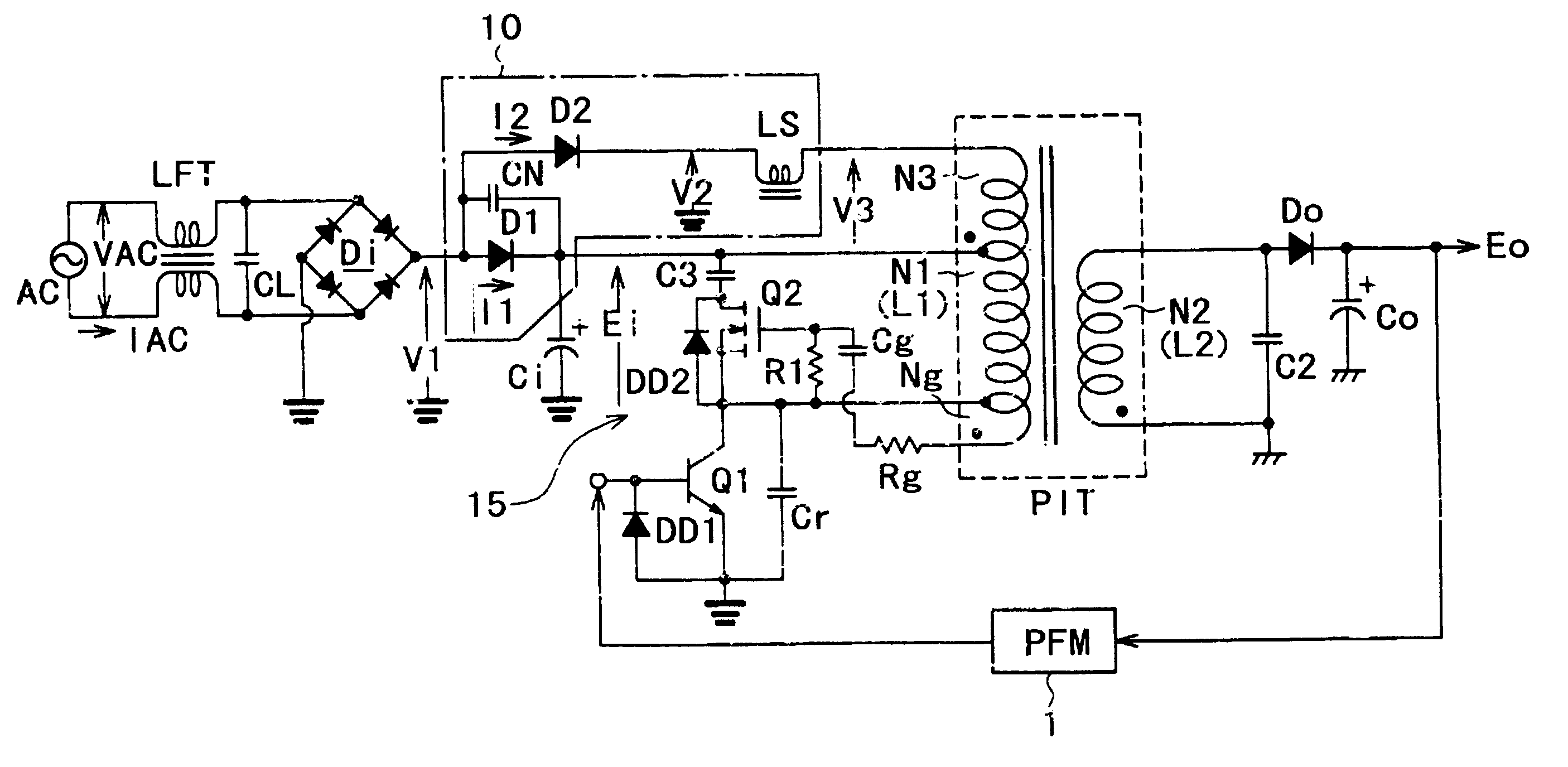
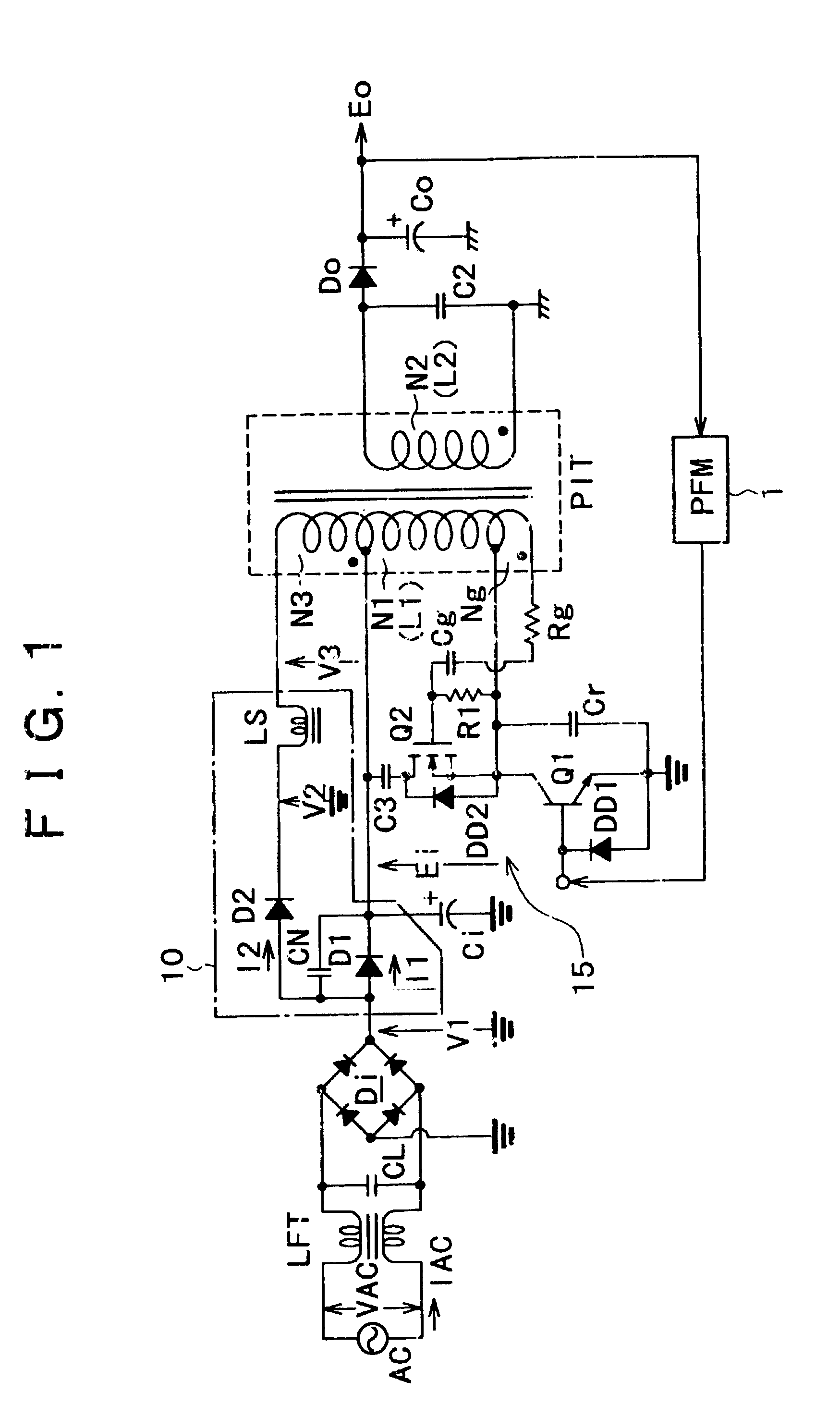
FIG. 1 shows a configuration of a switching power supply circuit to which the present invention is applied.

Referring to FIG. 1, the power supply circuit shown includes a switching converter of the voltage resonance type (a voltage resonance type converter) provided on the primary side. A power factor improving circuit 10 is provided for the voltage resonance type converter.

In the power supply circuit, a line filter transformer LFT and an across-the-line capacitor cl are provided for a commercial alternating-current power AC and form a line filter.

The power supply circuit further includes a bridge rectifier circuit Di for full-wave rectifying the commercial alternating-current power AC. A full-wave rectification output of the bridge rectifier circuit Di is charged into a smoothing capacitor Ci through the power factor improving circuit 10, and a rectified and smoothed voltage Ei is obtained across the smoothing capacitor Ci.

Before a configuration of the power factor improving circuit...

second embodiment

Now, another switching power supply circuit to which the present invention is applied is described.

The present embodiment achieves an object similar to that of the first embodiment described above and besides achieves improvement of the AC / DC power conversion efficiency (ηAC / DC) where the alternating-current input voltage VAC is a voltage of the 100 V type.

FIG. 7 shows the switching power supply circuit according to the second embodiment. It is to be noted that the same parts in FIG. 7 as that in FIG. 1 are denoted by the same reference characters in FIG. 1, and the detailed explanation therefor is omitted. The switching power supply circuit is different from the circuit of FIG. 1 principally in that it includes a voltage doubler rectifier circuit having a power factor improving function.

Referring to FIG. 7, the power supply circuit shown includes a switching converter of the voltage resonance type (a voltage resonance type converter) provided on the primary side. A rectification ci...

third embodiment

FIG. 8 shows a configuration of a further switching power supply circuit to which the present invention is applied.

Referring to FIG. 8, the power supply circuit shown includes a switching converter of the voltage resonance type (a voltage resonance type converter) provided on the primary side. A power factor improving circuit 10A is provided for the voltage resonance type converter. It is to be noted that the same parts in FIG. 8 as that in FIG. 1 are denoted by the same reference characters in FIG. 1.

Referring to FIG. 8, the power supply circuit shown includes a line filter transformer LFT and an across-the-line capacitor cl provided for a commercial alternating-current power AC and forming a line filter and a bridge rectifier circuit Di for full-wave rectifying the commercial alternating-current power AC in a similar manner as in the power supply circuit of FIG. 1. A rectification output from the bridge rectifier circuit Di is charged to a smoothing capacitor Ci through the power ...


PUM


Abstract

A switching power supply circuit ready for worldwide use is disclosed which suppresses a variation of a pulse voltage to be fed back when the alternating-current input varies. The switching power supply circuit includes a composite resonance type converter of a switching frequency control scheme wherein a voltage resonance pulse voltage generated in a primary side voltage resonance converter is fed back to a rectification diode through a high speed diode and an inductance or a transformer. An active clamp circuit is provided on the primary side to clamp the voltage resonance pulse voltage.

Description

BACKGROUND OF THE INVENTIONThis invention relates to a switching power supply circuit having a power factor improving function.Various power supply circuits in the form of a composite resonance type converter wherein a resonance type converter is provided on the primary side and a resonance circuit is provided also on the secondary side have been proposed by the assignee of the present application. Also various power circuits which include a power factor improvement circuit for improving the power factor of a composite resonance type converter have been proposed by the assignee of the present application.Among such power factor improving circuits, power factor improving circuits of the voltage feedback type have been proposed wherein a voltage resonance pulse voltage generated on the primary side is fed back to a smoothing capacitor to increase the conduction angle of alternating-current input current to improve the power factor. As power factor improving circuits of the type descri...

Claims


Application Information

Patent Timeline
Patent Type & Authority Patents(United States)
IPC IPC(8): H02M1/00H02M3/335H02M3/24H02M7/12H02M1/42H02M3/28
CPCH02M1/4208H02M3/335Y02B70/126Y02B70/10Y02P80/10
Inventor YASUMURA, MASAYUKI
Owner SONY CORP
Why Eureka
Try Eureka