On-line quality control of the key optical components in lithography lasers using laser induced fluorescence

a technology of optical components and lasers, applied in lasers, photometry, color/spectral properties measurements, etc., can solve the problems of limited life and poor laser bandwidth, and achieve the effect of improving the maintenance of these components

Inactive Publication Date: 2005-01-04
COHERENT GMBH
View PDF26 Cites 14 Cited by
  • Summary
  • Abstract
  • Description
  • Claims
  • Application Information

AI Technical Summary

Problems solved by technology

The color centers are reason for laser energy dropping, worse laser-bandwidth and limited life-time.

Method used


Image

  • On-line quality control of the key optical components in lithography lasers using laser induced fluorescence
  • On-line quality control of the key optical components in lithography lasers using laser induced fluorescence
  • On-line quality control of the key optical components in lithography lasers using laser induced fluorescence

Examples


Embodiment Construction

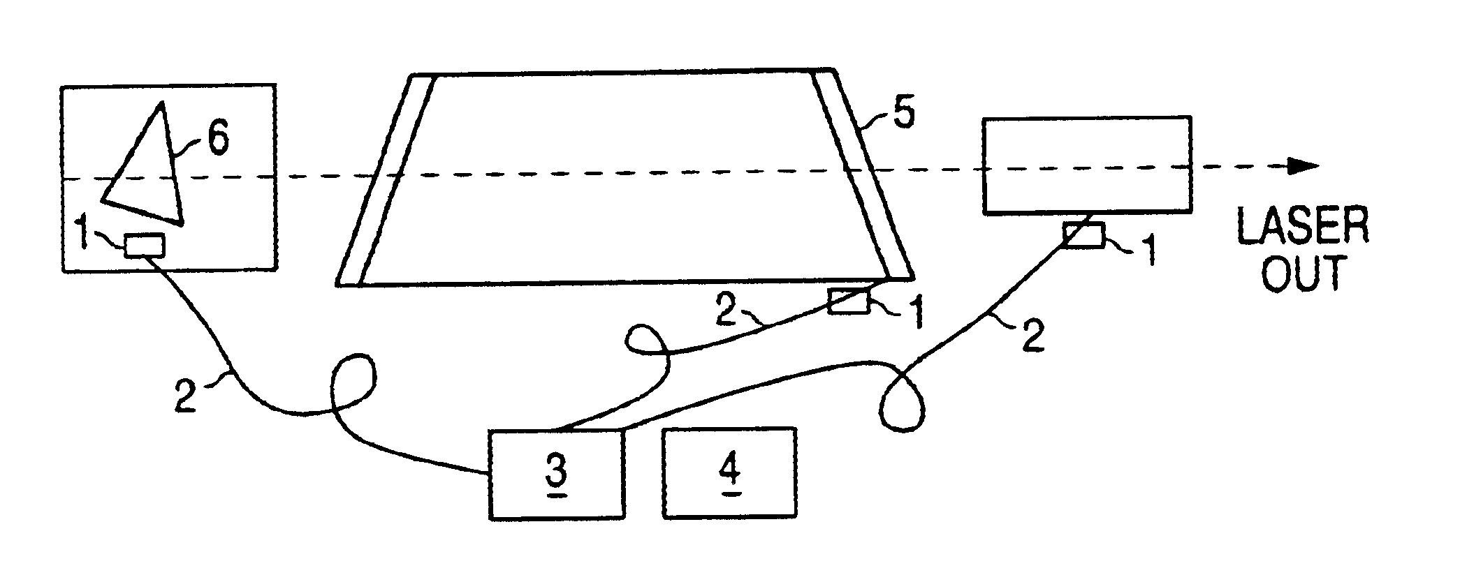
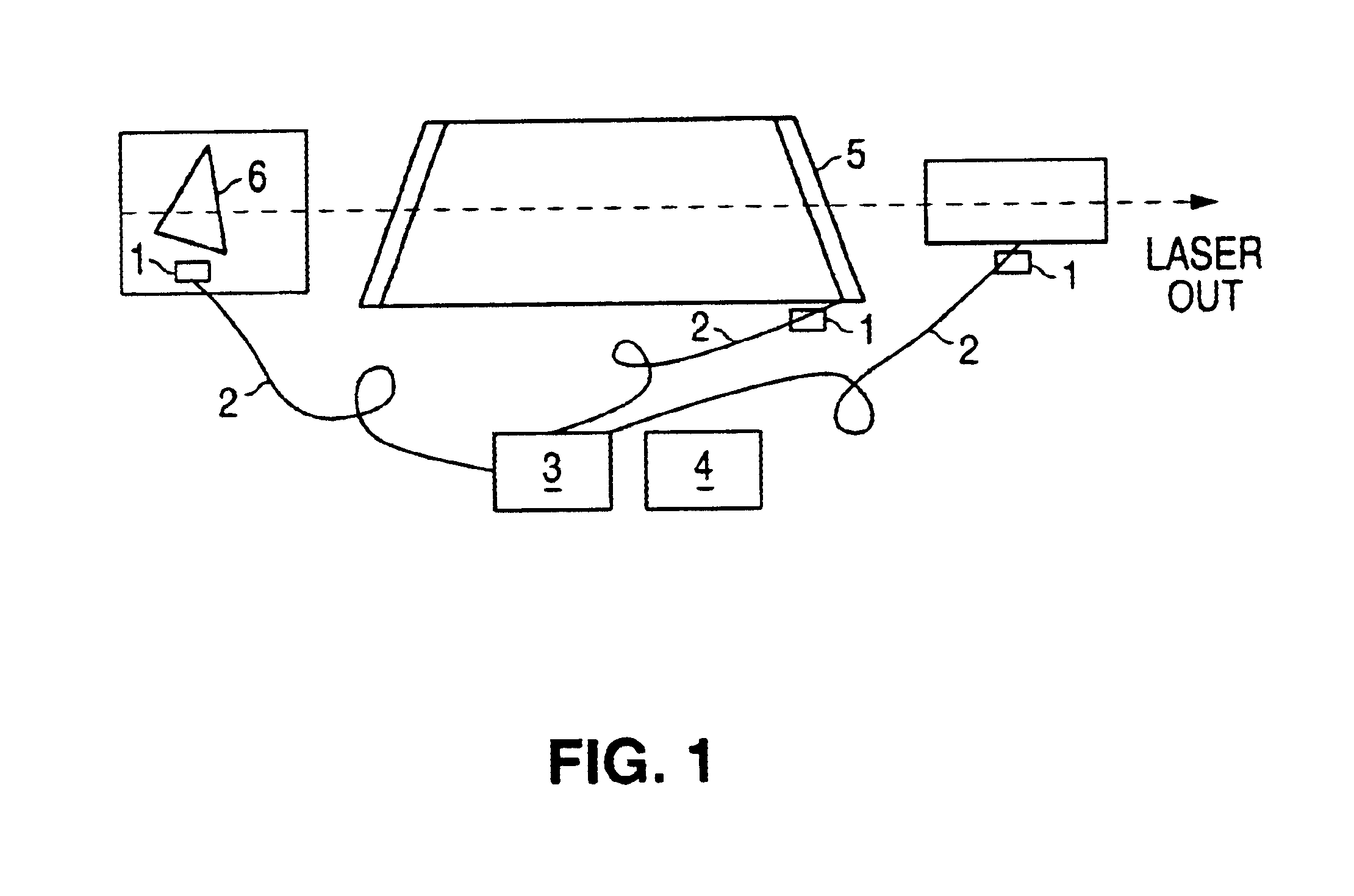
Some key optical component in lithography lasers (e.g. Prisms, Etalons, resonator windows, outcoupler etc.) are very sensitive to intensive UV radiation. Color center formation is in progress after UV illumination of these components. The color centers are reason for laser energy dropping, worse laser-bandwidth and limited live-time. To reduce the cost of ownership, the life time of optical components is an important parameter, mainly for high repetition lithography lasers used in steppers or scanners.

On-line monitoring of the color-center formation during operation of the lithography lasers detecting the induced fluorescence and investigation of the fluorescence spectrum can be helpful for maintenance of lithography lasers. Analysis of the detected induced fluorescence (peak wavelength, numbers of peak and their intensity) gives valuable information about optics quality, and reference for an eventually replacement (green and / or red fluorescence bands formation).

In FIG. 1 the fluore...


PUM

PropertyMeasurementUnit
volumeaaaaaaaaaa
volumeaaaaaaaaaa
wavelengthsaaaaaaaaaa

Abstract

Some of the key optical components of lithography lasers are very sensitive to intensive UV radiation. Intensive UV radiation can cause color center formation in these components. The color centers are reason for laser energy dropping, worse laser-bandwidth and limited life-time. The on-line monitoring of the color-center formation during operation of the lithography lasers detecting laser induced fluorescence and investigation of the fluorescence spectrum can be helpful for maintenance of lithography lasers. The fluorescence signal is analyzed and delivers information about optics quality.

Description

BACKGROUNDIn the present time is the quality of optical components in lithography systems not on-line tested. The common indicator used for replacement of optics is the laser counter. With the present invention the life-time of these expensive parts can be monitored and analyzed the induced fluorescence in these components during laser operation and the parts will only be exchanged when necessary. All of the following references, as well as the Background, Title and Summary of the Invention, are hereby incorporated by reference into the detailed description of the preferred embodiments as disclosing alternative features and elements not particularly set forth in the detailed description:1. M. Mizuguuchi et al.: Time-resolved photo luminescence for diagnosis of resistance to ArF excimer laser damage to CaF2 single crystals, J. Opt. Soc. Am. B 16, 1153-1159,19992. L. L. Clarke, M. S. Mendicino: Investigating Excimer Laser Induced Fluorescence in CaF2, 19993. Triebel, W. et. al.: Fused...

Claims


Application Information

Patent Timeline
Patent Type & Authority Patents(United States)
IPC IPC(8): G01N21/25H01J65/00H01J65/08H01S3/08G01N21/64G01N21/958
CPCG01N21/958G01N21/6402
Inventor LOKAI, PETERSEDDIGHI, FARID
Owner COHERENT GMBH
Why Eureka
Try Eureka