Chiral fiber grating

Inactive Publication Date: 2005-01-04
CHIRAL PHOTONICS
View PDF8 Cites 49 Cited by
  • Summary
  • Abstract
  • Description
  • Claims
  • Application Information

AI Technical Summary

Benefits of technology

In a fifth embodiment of the present invention, the first and second helices of the desired double helix structure are formed by a pair of grooves cut into sides of an optical fiber in a double helix pattern. The shape and size of the grooves may be selected as a matter of design choice without departing from the spirit of the invention.
In a sixth embodiment of the present invention, the first and second helices of the desired double helix structure are formed by a pair of grooves cut into sides of the chiral fiber in a double helix pattern and filled with a dielectric material having different optical properties from the material of the fiber core. The shape and size of the grooves and the dielectric material may be selected as a matter of design choice without departing from the spirit of the invention.
In

Problems solved by technology

However, FBGs based on conventional periodic structures are not easy to manufacture and suffer from a number of disadvantages.
Similarly, other types of desirable fiber gratings are difficult to fabricate using previously known techniques.
This approach limits the length of the resulting grating and also limits the index contrast produced.
Furthermore, such equipment requires perfect alignment of the interfering lasers and exa

Method used


Image

  • Chiral fiber grating
  • Chiral fiber grating
  • Chiral fiber grating

Examples


first embodiment

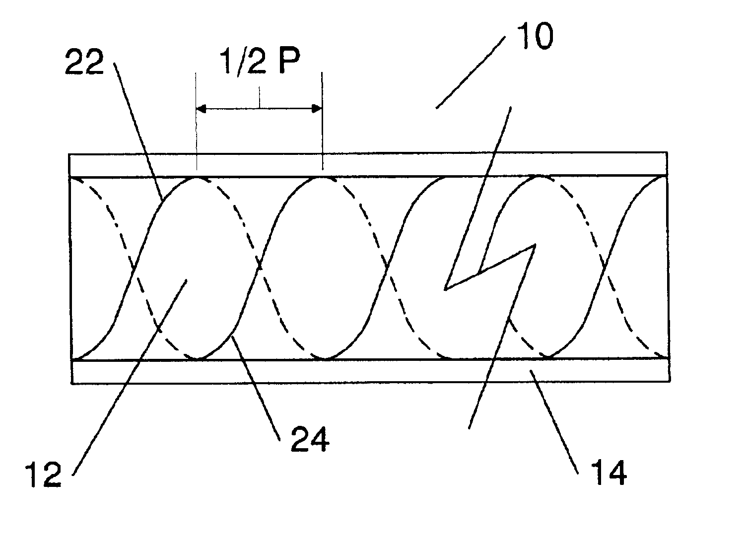
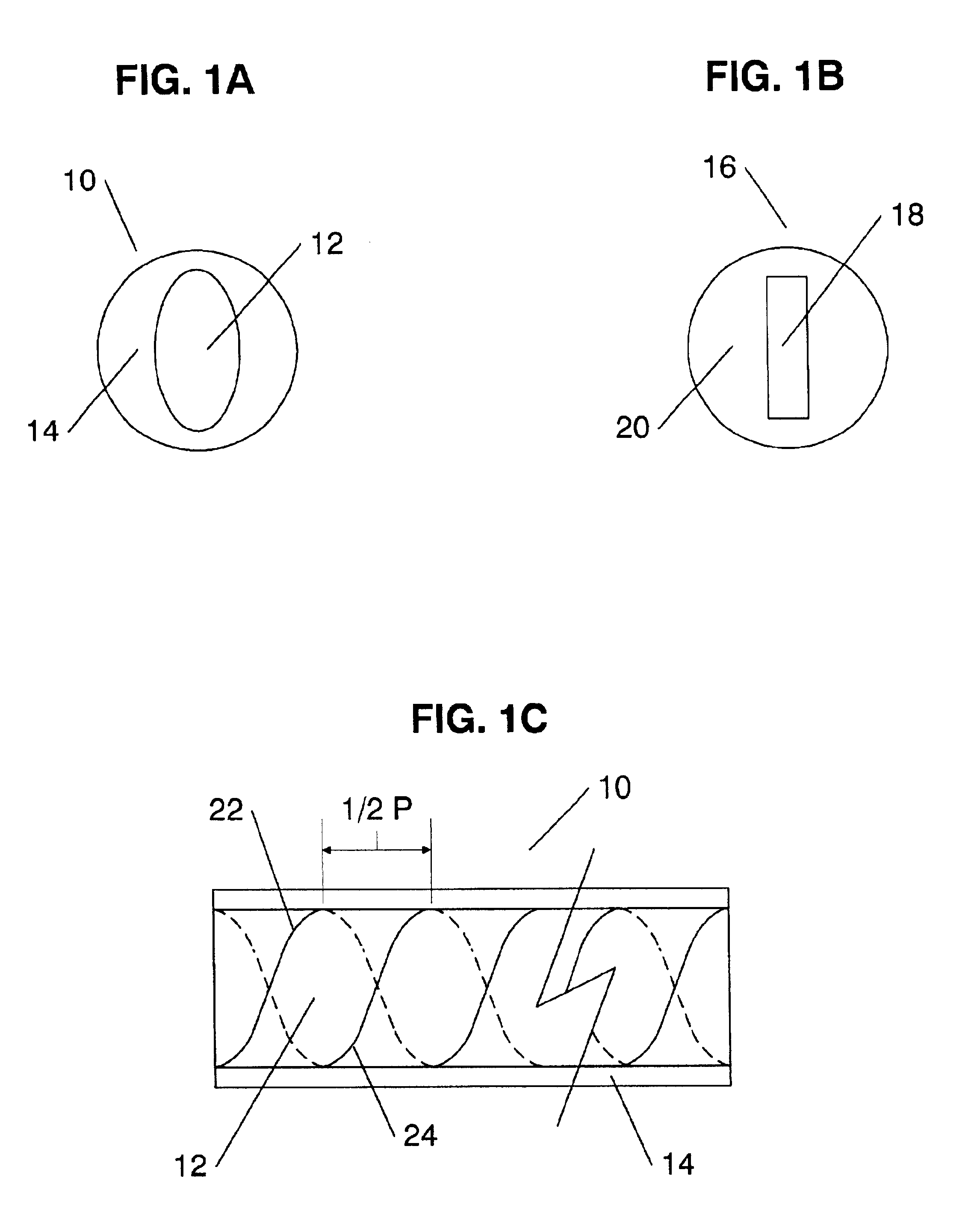
Referring now to FIGS. 1A to 1C, the present invention is shown where a chiral fiber 10 includes a core 12 with an oval cross-section and an optional cladding 14 surrounding the core 12. An alternate embodiment of the chiral fiber 10 is shown as a chiral fiber 16 with a rectangular core 18 and an optional cladding 20. It should be noted that the oval and rectangular cross sections of FIGS. 1A and 1B are shown by way of example only and other non-circular cross sectional shapes having 180 degree cross-sectional symmetry may be used as a matter of design choice without departing from the spirit of the invention.

FIG. 1C shows a cross section of the chiral fiber 10 twisted about its longitudinal axis. Because the core 12 has non-circular 180 degree cross-sectional symmetry, when the chiral fiber 10 is twisted about its longitudinal axis, a double helix structure is thereby formed, with a second helix 24 being displaced forward from a first helix 22 by one half of the pitch of the chiral...

second embodiment

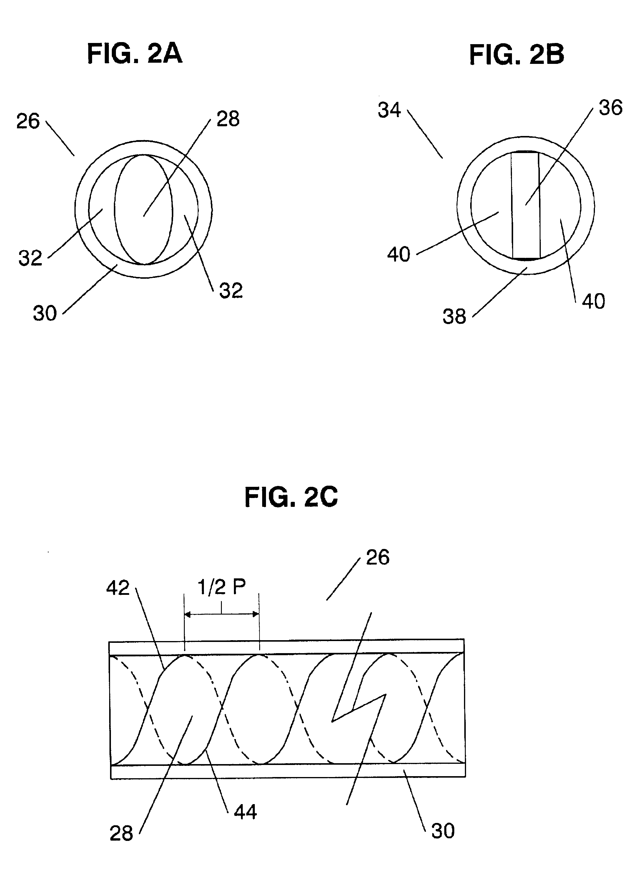
Referring now to FIGS. 2A to 2C, the present invention is shown where a chiral fiber 26 includes a core 28 with an oval cross-section and an optional hollow cylindrical cladding 30 either surrounding or in contact with the core 28. A dielectric material 32 is disposed within the empty space between the core 28 and an inner surface of the cladding 20. The dielectric material 32 may be any dielectric substance with different optical characteristics from the core 28. For example, the material 32 may be air, dielectric fluid, or glass with different properties from the core 28. An alternate embodiment of the chiral fiber 26 is shown as chiral fiber 34 with a rectangular core 36, an optional hollow cylindrical cladding 38 and a dielectric material 40 disposed in the empty space between the core 36 and the inner surface of the cladding 38. It should be noted that the oval and rectangular cross sections of FIGS. 2A and 2B are shown by way of example only and other non-circular cross sectio...

third embodiment

Referring now to FIGS. 3A and 3B, the present invention is shown where chiral fiber 44 includes a core 46 that is composed of a first quarter-cylindrical portion 48 of a first material in contact on each side with a second and third quarter cylindrical portions, 52, 54 composed of a second material, and a fourth quarter-cylindrical portion 50 of the first material contacting its sides with the second and third quarter cylindrical portion 52, 54 sides that are not in contact with the first quarter-cylindrical portion 48; where all vertices of the first, second, third and fourth quarter-cylindrical portions 48, 50, 52, 54 are aligned with the central longitudinal axis of the chiral fiber 44. Each of the first and second materials have different optical properties. The first and second materials may be selected from a variety of glass and other dielectric substances as a matter of design choice. For example, one of the materials may be air. The core 46 is enclosed by an optional claddi...


PUM


Abstract

A a chiral fiber grating mimicking a cholesteric liquid crystal structure to achieve fiber Bragg grating properties, is provided. The chiral fiber grating includes a first and a second helical structures disposed along its central longitudinal axis, where the second helical structure is identical in orientation to the first helical structure but is shifted by one half of the structure's pitch forward. In another embodiment of the invention, only a single helical structure is disposed along the fiber to create an optically resonant chiral fiber.

Description

FIELD OF THE INVENTIONThe present invention relates generally to fiber grating type structures, and more particularly to an optical fiber grating having chiral properties.BACKGROUND OF THE INVENTIONCoherent laser beam sources have many industrial applications—for example in communication systems, in information processing, and in holographic displays. There are two previously known types of one-dimensional (1D) photonic band gap (PBG) structures: (1) periodic layered media, and (2) cholesteric liquid crystals (CLCs). In both of these systems the wavelength inside the medium at the center of the band gap is twice the period of the structure in question. In CLC structures, the band gap exists only for the circular polarized component of light, which has the same sense of rotation as the structure. The second circular component is unaffected by the structure. The first type of structure has been implemented in optical fibers and is known as a fiber Bragg grating (FBG). However, the sec...

Claims


Application Information

Patent Timeline
IPC IPC(8): G02B6/10G02B6/02
CPCG02B6/02085G02B6/021G02B2006/0209G02B6/105G02B6/024
Inventor KOPP, VICTOR IL'ICHGENACK, AZRIEL ZELIG
Owner CHIRAL PHOTONICS
Why Eureka
Try Eureka