State-of-device remote monitoring system

a monitoring system and state-of-device technology, applied in the direction of electric controllers, program control, instruments, etc., can solve the problems of cost of introducing the cable, the inability to realistically do the man-based process, and the difficulty of extending the new cabl

Inactive Publication Date: 2005-01-04
MITSUBISHI ELECTRIC CORP
View PDF30 Cites 83 Cited by
  • Summary
  • Abstract
  • Description
  • Claims
  • Application Information

AI Technical Summary

Problems solved by technology

The state-of-device remote monitor system described above might, however, be operated by a method of monitoring the device state online at all times. In such a case, it is not realistic that the man-based process is done as an intermediary process between a data measurement by the detector and a judgment for presuming the device state on the basis of the measured data.
Thus, if the monitor of the state of the device 21 needs the extension of the cable, there arises a problem related to a cost for introducing the cable even if possible of extending the cable.
Moreover, the monitor target device 21 may be installed at a high place or on the underground within the plant or within a storage container in a nuclear power plant, wherein it is considered difficult to extend a new cable.
Therefore, a problem is that the extension of the cable becomes an obstacle against the introduction.

Method used


Image

  • State-of-device remote monitoring system
  • State-of-device remote monitoring system
  • State-of-device remote monitoring system

Examples


embodiment 1

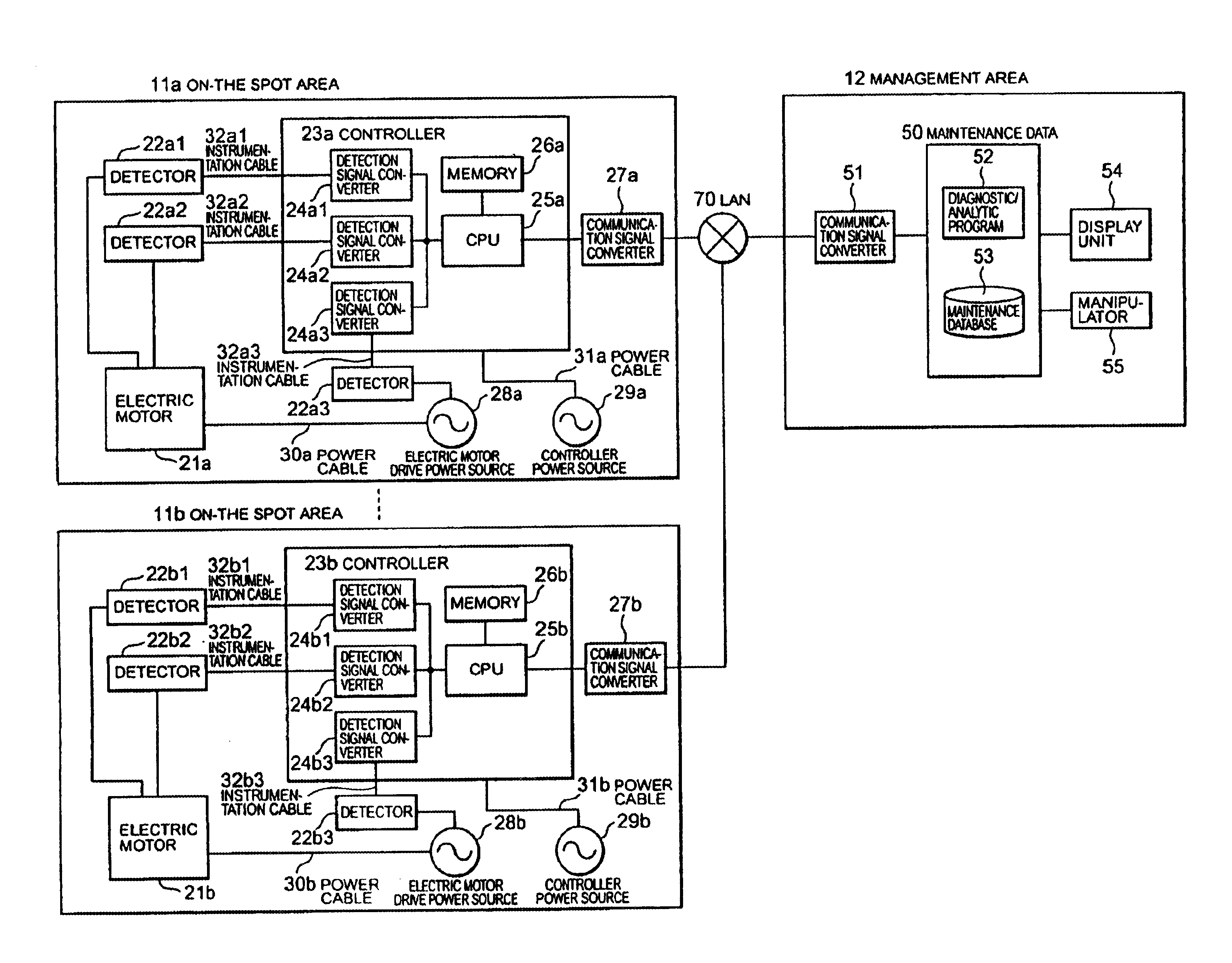
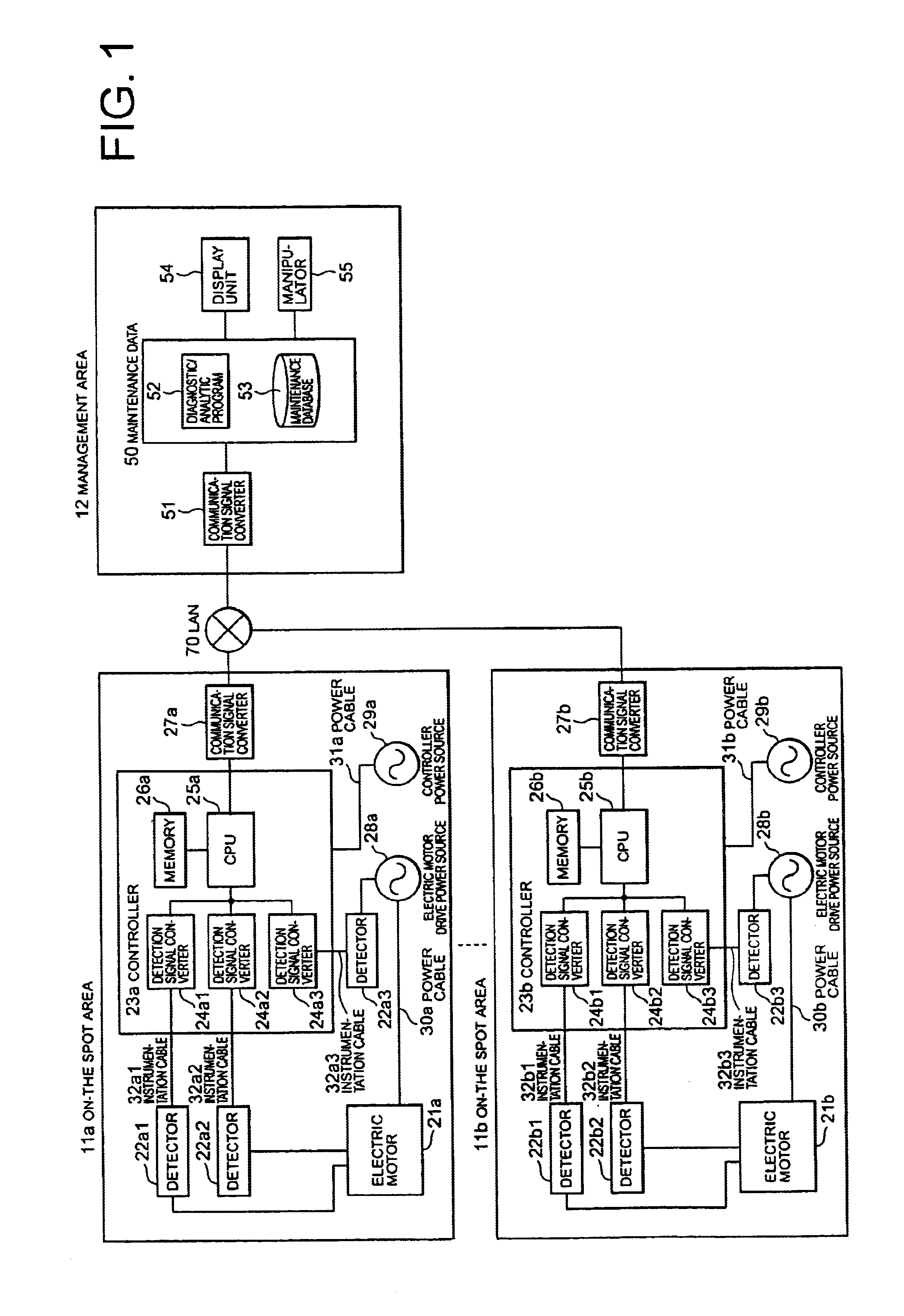
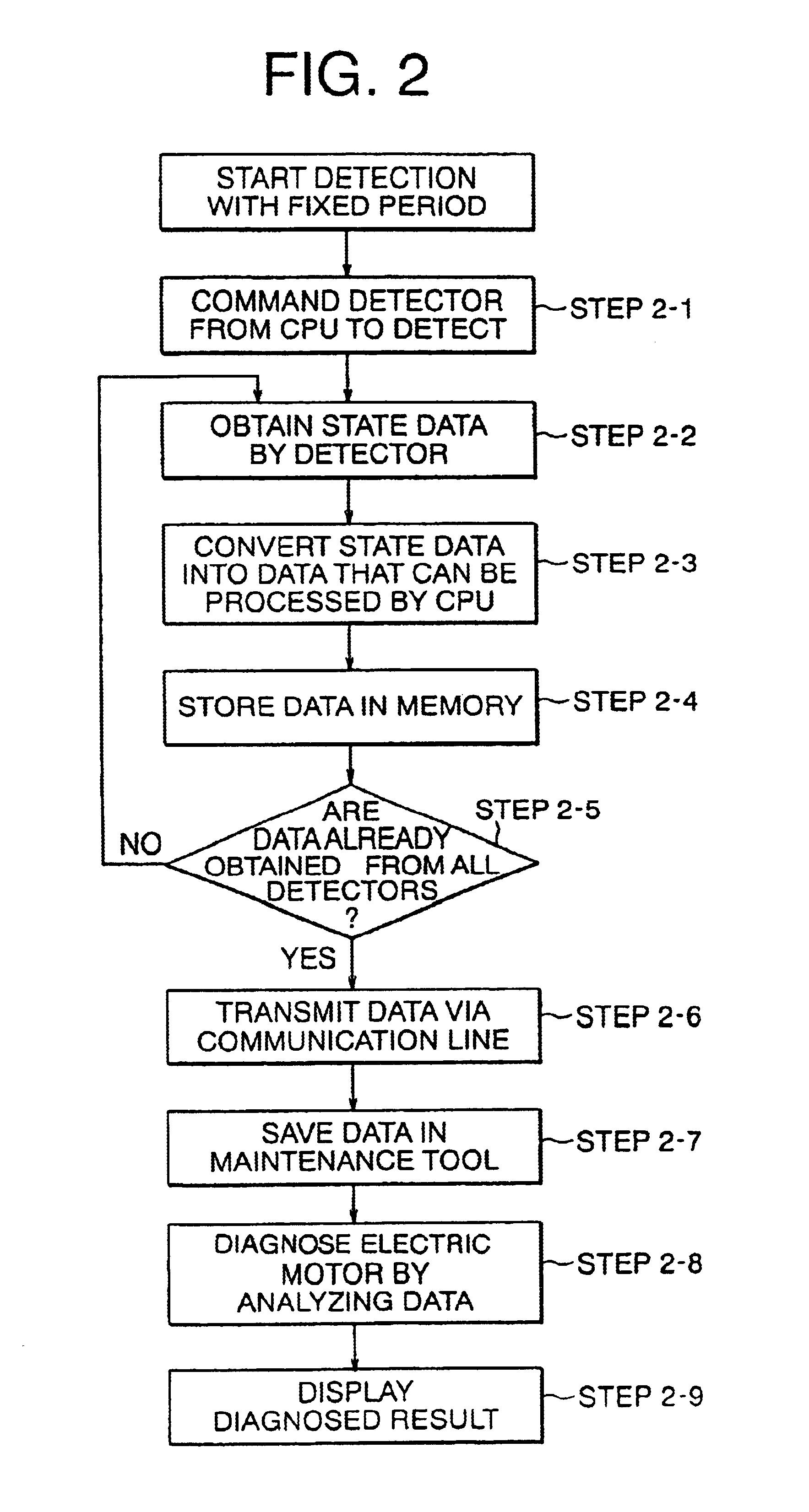
FIG. 1 is a diagram showing an architecture of a state-of-device remote monitor system in accordance with the present invention. FIG. 2 is a flowchart showing an operation in Embodiment 1.

As shown in FIG. 1, the architecture in Embodiment 1 is configured by a single or a plurality of on-the-spot areas 11a, 11b and a management area 12 existing at some distance from the on-the-spot areas 11a, 11b.

In the on-the-spot area 11a, an electric motor 21a is supplied with the electricity via a power cable 30a from a power source 28a. States of the electric motor 21a and the power source 28a are detected by a plurality of detectors 22a1, 22a2, 22a3 attached thereto, and detection signals thereof are transmitted to a controller 23a via instrumentation cables 32a1, 32a2, 32a3.

Detection signal converters 24a1, 24a2, 24a3 convert the signals transmitted via these instrumentation cables 32a1, 32a2, 32a3 into digital signals that can be processed by a CPU 25a. The detection signals and instructions...

embodiment 2

FIG. 3 illustrates an embodiment different from Embodiment 1. According to Embodiment 1, the data transmission between the on-the-spot area 11a and the management area 12 involves applying the LAN 70. According to Embodiment 2, however, as shown in FIG. 3, the data transmission between the on-the-spot area 11a and the management area 12 involves applying a radio system.

In Embodiment 2, a hardware architecture between the controller 23a and the maintenance tool 50 is different from that in Embodiment 1, and is configured by a radio signal converter 33a for converting the detection data outputted from the controller 23a in the on-the-spot area 11a into radio signals, and a radio signal converter 56 for converting the radio signals in the management area 12 into data signals in the management area 12.

The discussion will be focused on a different system operation of the state-of-device remote monitor system in Embodiment 2 from Embodiment 1. The detection data obtained from all the dete...

embodiment 3

FIG. 5 shows an embodiment different from Embodiments 1 and 2. According to Embodiments 1 and 2, the data transmission between the on-the-spot area 11a and the management area 12 involves applying the LAN 70 and the radio 71. In Embodiment 3, however, the data transmission involves applying, as shown in FIG. 5, a public telephone line 73.

A different architecture in Embodiment 3 from Embodiment 1 is provided between the controller 23a and the maintenance tool 50, and is configured by a router 34a for transferring the signals outputted from the controller 23a in the on-the-spot area 11a to the telephone line 73, and a router 57 for transferring the signals from the telephone line 73 to the maintenance tool 50 in the management area 12. Note that the telephone line 73 is a part of the existing infrastructures.

If the telephone line is not connected, a connection of the telephone line is established by dial-up accesses of the routers 34a and 57. Further, if the telephone line is classifi...


PUM


Abstract

A state-of-device remote monitor system capable of applying a general-purpose line as a transmission line for transmitting detection signals of a state of a device, comprises an on-the-spot area, and a management area. The on-the-spot area includes an electric device, a detector for detecting a device state of the electric device, and a first communication signal converter for converting detection data obtained by the detection of the detector into communication signals, and transmitting the communication signals. The management area includes a second communication signal converter for converting the communication signals received from the first communication signal converter into the detection data before being converted by the first communication signal converter, a maintenance tool having a diagnostic / analytic program for analyzing the device state from the detection data converted by the second communication signal converter, and a maintenance database stored with data necessary for the analysis by the diagnostic / analytic program and a diagnosed result, and a display unit for displaying the diagnosed result obtained by the analysis by the maintenance tool.

Description

This application is based on Application No. 2001-259863, filed in Japan on Aug. 29, 2001, the contents of which are hereby incorporated by reference.BACKGROUND OF THE INVENTION1. Field of the InventionThe present invention relates generally to a state-of-device remote monitor system, and more particularly to a state-of-device remote monitor system for remotely obtaining various categories of data about a temperature, vibrations and so on in an operating state of an electric device such as an electric motor.2. Description of the Related ArtIn a large-scale plant such as a power plant, water treatment plant, etc. which often use electric motors, if something abnormal is detected by monitoring a device state of the electric motor, a generator or a transformer installed in the plant, it is important in terms of reliability of the plant and enhancing operating ratio to obtain details of this abnormality.An introduction of a state-of-device remote monitor system for observing various ite...

Claims


Application Information

Patent Timeline
Patent Type & Authority Patents(United States)
IPC IPC(8): G05B23/02H04M11/00G08B25/00H04Q9/00
CPCG05B23/0264G05B23/0267G05B2219/13G05B2223/06
Inventor HATTORI, TAKAYUKIIKEDA, IKUOTSUTSUMI, RIICHIRO
Owner MITSUBISHI ELECTRIC CORP
Why Eureka
Try Eureka