Fuel tank tester

US6840089B2Inactive Publication Date: 2005-01-11HICKOK

Image

  • Fuel tank tester
  • Fuel tank tester
  • Fuel tank tester

Examples


Embodiment Construction

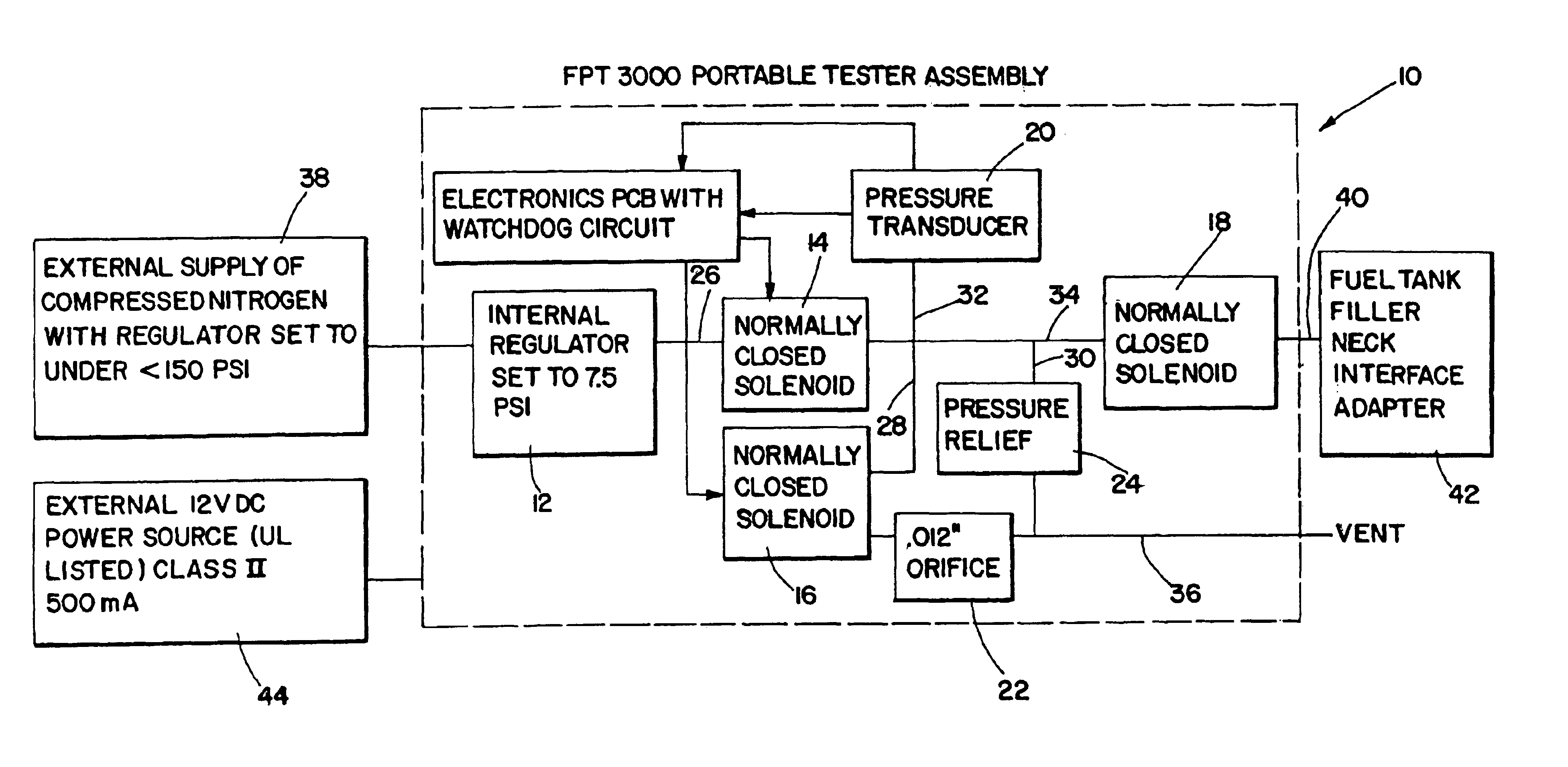
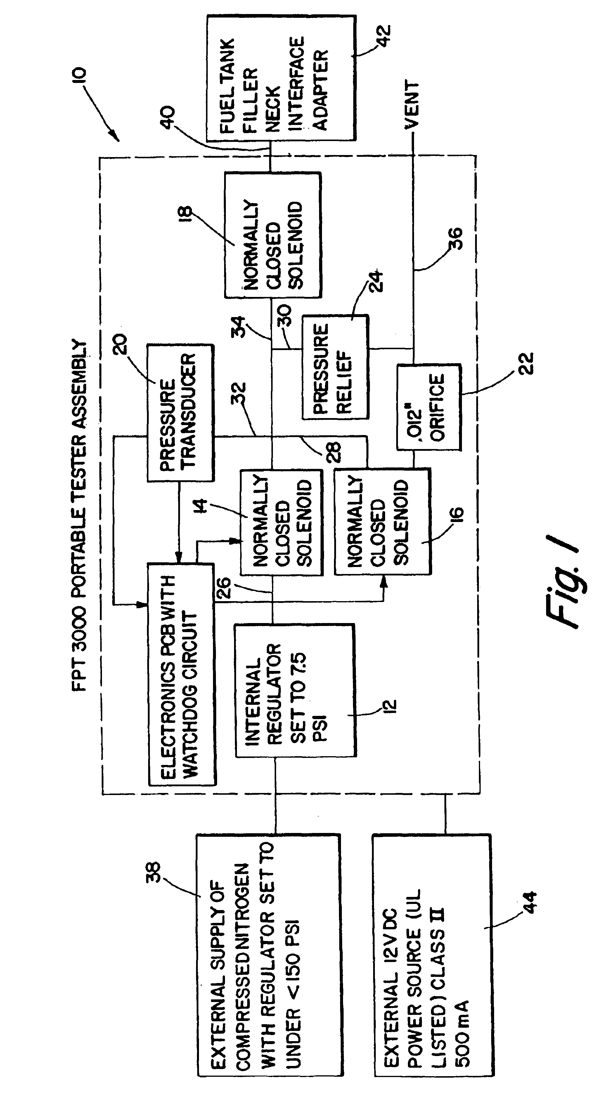
Referring now to the drawings where the illustrations are for the purposes of describing the preferred embodiment of the present invention and are not intended to limit the invention described herein, FIG. 1 is a schematic drawing illustrating the pneumatic circuit for the fuel tank tester 10 of the present invention. As such, the fuel tank tester 10 includes a pressure regulator 12, normally closed solenoid valves 14, 16 and 18, a pressure transducer 20, a reference orifice 22 and a pressure relief valve 24. The output of the pressure regulator 12 is connected to the input to normally closed solenoid valve 14 via tubing 26. The output of normally closed solenoid valve 14 is connected to the inputs to normally closed solenoid valve 16, pressure relief valve 24, pressure transducer 20 and normally closed solenoid valve 18 via tubings 28, 30, 32 and 34, respectively. An inline air filter (not shown) may be connected in tubing 28 between the output of normally closed solenoid valve 14 ...


PUM


Abstract

An apparatus and a method for testing the integrity of fuel tanks for leaks are disclosed. A microprocessor controls the pressurization of the fuel tank and then selectively allows the gas within the fuel tank to decay through any leaks within the tank or through the combination of the leaks within the tank and a reference orifice. By computing and comparing the time required for the tank pressure to decay between predetermined pressure levels due to any tank leaks with a standard decay time, a determination can be made whether the leakage rate through the tank is acceptable. Greater resolution, if necessary, is provided by computing the ratio of the time required for the tank pressure to decay between predetermined pressure levels through the combination of any tank leaks and a reference orifice versus only through the tank leaks and compares same against a standard ratio to determine whether the tank leakage rate is acceptable.

Description

TECHNICAL FIELDThe present invention relates, in general, to a testing device for a fuel tank and, more particularly, to a testing device which accurately and rapidly measures the rate of leakage of fuel vapors through the fuel tank and compares same against a leakage rate standard so that those tanks with leakage rates that exceed the standard can be readily identified.BACKGROUND ARTThe testing of the functional systems of vehicles has become quite sophisticated and requires extensive testing procedures to ensure that the vehicle components are operating properly and that the overall system performance is in accordance with specific guidelines. The Federal Environmental Protection Administration (EPA) has established extensive regulations limiting emissions from motor vehicles. One area of particular interest is the vehicle fuel system. The loss of fuel through evaporation to the atmosphere is wasteful and environmentally harmful since fuel vapors contribute to unwanted hydrocarbon...

Claims


Application Information

Patent Timeline
11 Jan 2005
Publication
US6840089B2
IPC
G01M3/32; G01M3/00
CPC
G01M3/3209; G01M3/007
Inventors
DOCY, MICHAEL J.; HART, GEORGE R.