Internal exhaust gas recirculation amount estimation system of internal combustion engines

Active Publication Date: 2005-01-11
NISSAN MOTOR CO LTD
View PDF10 Cites 63 Cited by
  • Summary
  • Abstract
  • Description
  • Claims
  • Application Information

AI Technical Summary

Benefits of technology

Accordingly, it is an object of the invention to provide an internal EGR amount estimation system for an internal combustion en

Problems solved by technology

However, in particular in a transient engine operating state that at least one of the engine load, engine speed, air/fuel mixture ratio, and intake-manifold pressure remarkably varies, it is difficult to univocally exactly estimate the amount of internal EGR from the valve overlap p

Method used


Image

  • Internal exhaust gas recirculation amount estimation system of internal combustion engines
  • Internal exhaust gas recirculation amount estimation system of internal combustion engines
  • Internal exhaust gas recirculation amount estimation system of internal combustion engines

Examples


Embodiment Construction

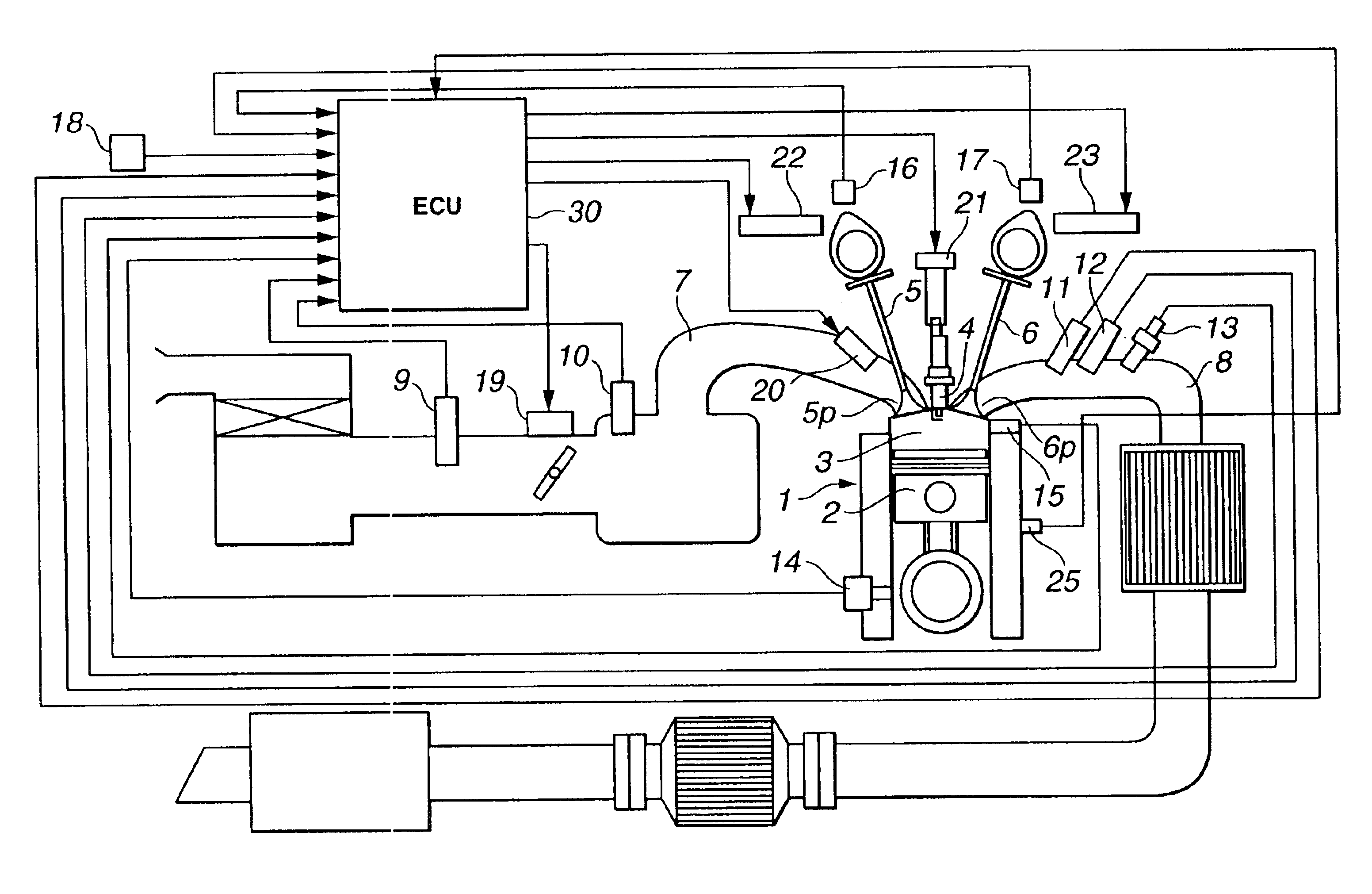
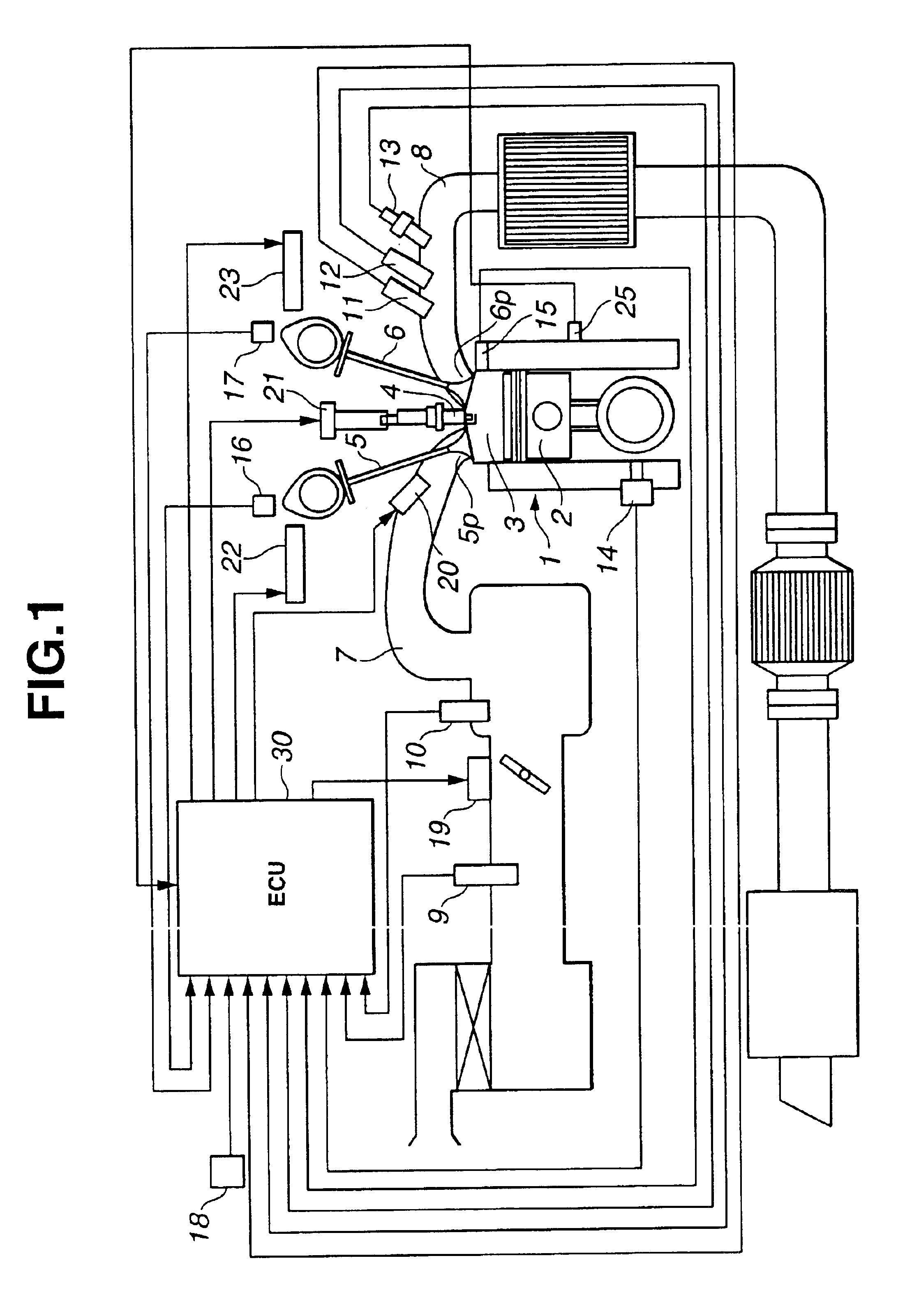
Referring now to the drawings, particularly to FIG. 1, the internal exhaust gas recirculation (EGR) amount estimation system is exemplified in a double-overhead-camshaft internal combustion engine 1 employing a variable valve timing device enabling a valve characteristic, such as an engine valve open timing and an engine valve closure timing, to be varied. A combustion chamber 3 is defined between the inner wall of the cylinder head and a reciprocating piston 2, fitted to each engine cylinder. An intake valve 5, which opens and closes an intake port 5p of combustion chamber 3, and an exhaust valve 6, which opens and closes an exhaust port 6p of combustion chamber 3, are provided in such a manner as to surround a spark plug 4 mounted on the cylinder head. An exhaust valve characteristic (containing an exhaust valve open timing EVO and an exhaust valve closure timing EVC) is variably controlled by changing a phase of an exhaust-valve cam relative to its camshaft by means of an electro...


PUM


Abstract

An internal exhaust gas recirculation amount estimation system calculates an in-cylinder temperature at an exhaust valve closure timing, an in-cylinder pressure at the exhaust valve closure timing, and a gas constant corresponding to a change in a composition of exhaust gas, based on an air-fuel mixture ratio. An exhaust valve closure timing in-cylinder residual gas amount is calculated based on at least the in-cylinder temperature, the in-cylinder pressure, and the gas constant. Also calculated is a valve overlap period blow-back gas amount, which is defined as a quantity of gas flow from one of intake and exhaust ports via a combustion chamber to the other port during a valve overlap period. An internal exhaust gas recirculation amount is calculated based on the exhaust valve closure timing in-cylinder residual gas amount and the valve overlap period blow-back gas amount.

Description

TECHNICAL FIELDThe present invention relates to an internal exhaust gas recirculation (internal EGR) amount estimation system for internal combustion engines, and specifically to the improvement of estimation of internal EGR relating to a valve overlap period during which both of intake and exhaust valves are open together.BACKGROUND ARTAs is generally known, in order to attain both a reduction in the amount of nitrogen oxides (NOx) produced by an internal combustion engine, based on an increase in inert gases contributing to a reduced combustion temperature, and a reduction in pumping loss contributing to a reduced fuel consumption, a spark-ignition internal combustion engine often uses a variable valve operating mechanism so as to actively increase a valve overlap that the open periods of intake and exhaust valves are overlapped, and consequently to increase the amount of internal EGR. In such a case, it is more desirable to simultaneously optimize or compensate for an ignition ti...

Claims


Application Information

Patent Timeline
IPC IPC(8): F02D21/00F02D41/00F02D21/08F01L1/20F02D13/02F02M25/07
CPCF01L1/20F02D13/0207F02D35/023F02D35/025F02M25/0752F02M25/0754F02D41/0062F01L2800/00Y02T10/47F02D2041/001Y02T10/18F02M26/01F02M26/47Y02T10/12Y02T10/40
Inventor KOSEKI, TAKAHISAOSHIMI, YOUICHINAGAISHI, HATSUO
Owner NISSAN MOTOR CO LTD
Why Eureka
Try Eureka