Surge absorber flow regulation for modular pressure swing adsorption

a pressure swing adsorption and flow regulation technology, applied in the field of apparatus for separating gas fractions, can solve the problems of reducing the efficiency and yield of the gas separation process, rotary valves have considerable dead volume for flow distribution and collection, and the system is often difficult and expensive to implement, so as to reduce the dead volume of the adsorption. , the effect of contributing to the dead volume of the adsorption

Inactive Publication Date: 2005-01-11
AIR PROD & CHEM INC
View PDF17 Cites 59 Cited by
  • Summary
  • Abstract
  • Description
  • Claims
  • Application Information

AI Technical Summary

Benefits of technology

Since the orifices providing the valving function are immediately adjacent to the ends of the flow paths, the dead volume associated with prior art distribution manifolds is substantially reduced. Also, since the compartments communicating with the first and second valve surfaces are external to the valving function, the compartments do not contribute to dead volume of the adsorbers. As a result, high frequency pressure / vacuum swing adsorption is possible.

Problems solved by technology

However, this system is often difficult and expensive to implement due to the complexity of the valving required.
Further, the adsorbent beds are often exposed to variations in pressure and gas flow, thereby reducing the efficiency and yield of the gas separation process.
However, these prior art rotary valves have considerable dead volume for flow distribution and collection, and expose the adsorbent beds to pulsations in pressure and gas flow.
As a result, the rotary valves have poor flow distribution, particularly at high cycle frequencies.
However, with these systems, the vacuum pumps are subjected to large pressure pulsations, stressing the compression machinery and causing large fluctuations in overall power demand.
Because centrifugal or axial compression machinery cannot operate under such unsteady conditions, rotary lobe machines are typically used in such systems.
However, such machines have lower efficiencies than modern centrifugal compressors / vacuum pumps working under steady state conditions.

Method used


Image

  • Surge absorber flow regulation for modular pressure swing adsorption
  • Surge absorber flow regulation for modular pressure swing adsorption
  • Surge absorber flow regulation for modular pressure swing adsorption

Examples


Embodiment Construction

FIGS. 1, 2, 3 and 4

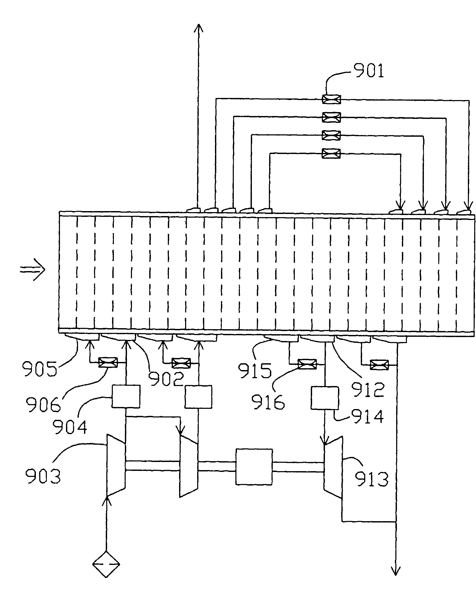
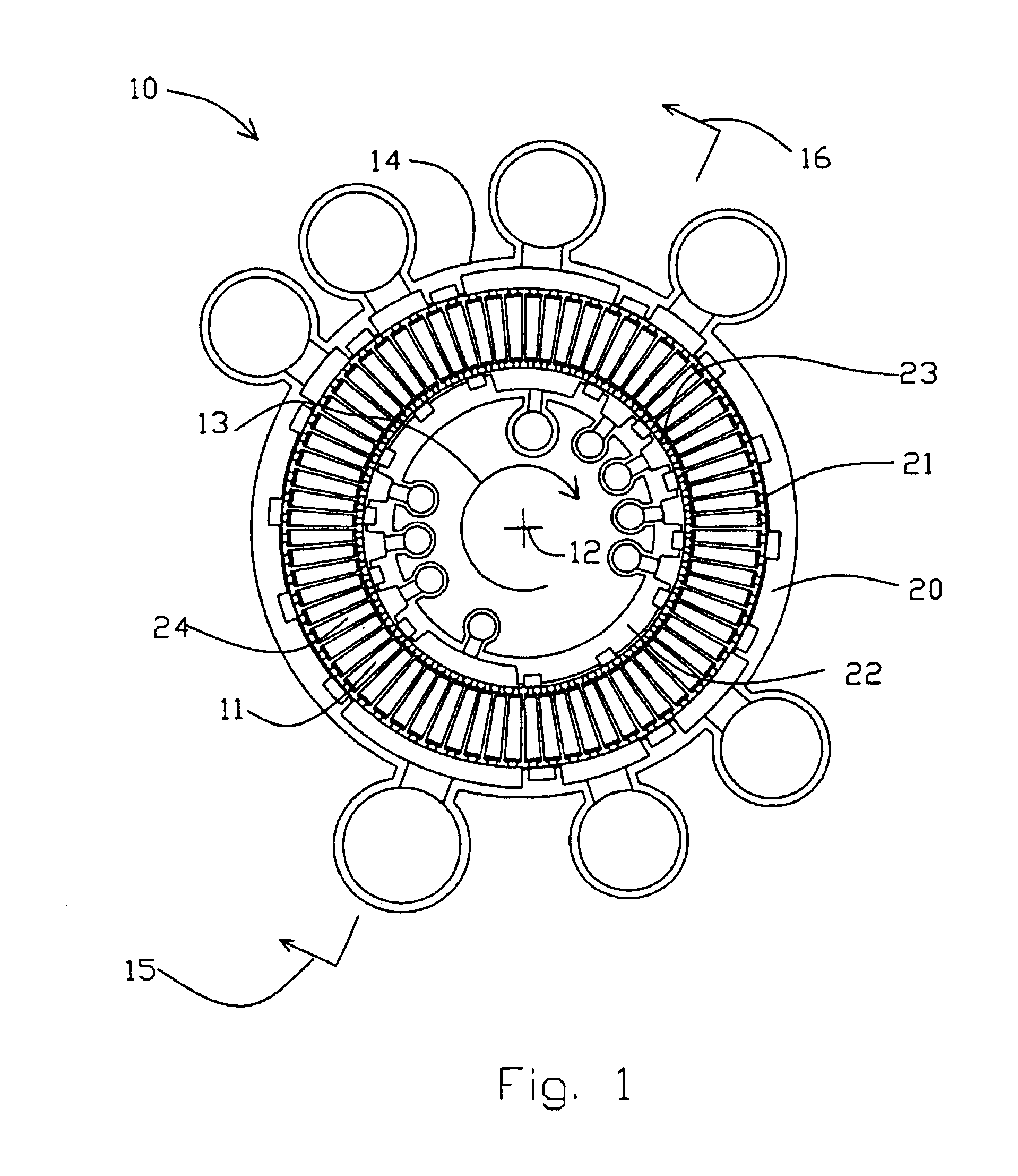
A rotary module 10 according to the present invention is shown in FIGS. 1, 2, 3 and 4. The module includes a rotor 11 revolving about axis 12 in the direction shown by arrow 13 within stator 14. In general, the apparatus of the invention may be configured for flow through the adsorber elements in the radial, axial or oblique conical directions relative to the rotor axis. However, for operation at high cycle frequency, radial flow has the advantage that the centripetal acceleration will lie parallel to the flow path for most favorable stabilization of buoyancy-driven free convection, as well as centrifugal clamping of granular adsorbent with uniform flow distribution.

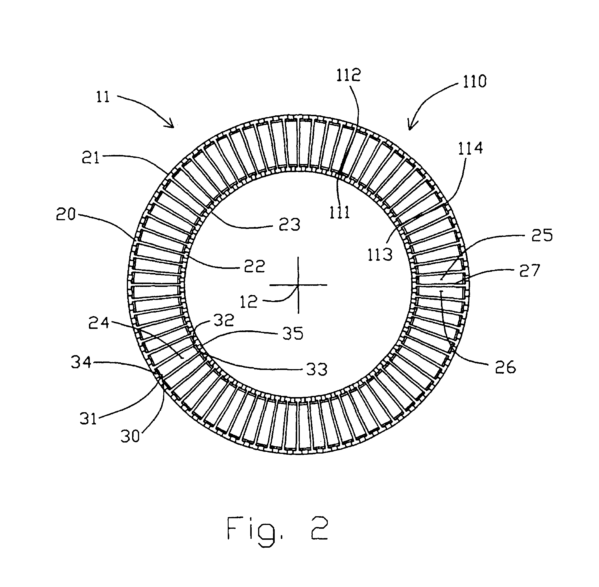
As shown in FIG. 2, the rotor 11 is of annular section, having concentrically to axis 12 an outer cylindrical wall 20 whose external surface is first valve surface 21, and an inner cylindrical wall 22 whose internal surface is second valve surface 23. The rotor has (in the plane of the section defined ...


PUM

PropertyMeasurementUnit
pressureaaaaaaaaaa
lengthaaaaaaaaaa
volumeaaaaaaaaaa

Abstract

A gas separation system includes a stator, and a rotor rotatably coupled to the stator, and at least one surge absorber in communication with the stator. The stator includes a stator valve surface and a plurality of function compartments opening into the stator valve surface. The rotor includes a rotor valve surface in communication with the stator valve surface, and a plurality of flow paths for receiving adsorbent material therein. The rotor also includes a plurality of apertures provided in the rotor valve surface and in communication with the flow paths for cyclically exposing the flow paths to the function compartments. The surge absorbers are configured to reduce pressure variations in the function compartments and to maintain each function compartment at one of a plurality of discrete pressure levels. In this manner, substantially uniform gas flow can be maintained through the function compartments and the flow paths without recourse to multistage compression machinery.

Description

FIELD OF THE INVENTIONThe present invention relates to an apparatus for separating gas fractions from a gas mixture having multiple gas fractions. In particular, the present invention relates to a rotary valve gas separation system having a plurality of rotating adsorbent beds disposed therein for implementing a pressure swing adsorption process for separating out the gas fractions.BACKGROUND OF THE INVENTIONPressure swing adsorption (PSA) and vacuum pressure swing adsorption (VPSA) separate gas fractions from a gas mixture by coordinating pressure cycling and flow reversals over an adsorbent bed which preferentially adsorbs a more readily adsorbed component relative to a less readily adsorbed component of the mixture. The total pressure of the gas mixture in the adsorbent bed is elevated while the gas mixture is flowing through the adsorbent bed from a first end to a second end thereof, and is reduced while the gas mixture is flowing through the adsorbent from the second end back t...

Claims


Application Information

Patent Timeline
Patent Type & Authority Patents(United States)
IPC IPC(8): B01D53/047B01D53/04B01D53/06
CPCB01D53/0431B01D53/047B01D53/06B01D2259/4068B01D2256/12B01D2257/102B01D2259/40005B01D2253/108
Inventor KEEFER, BOWIE G.
Owner AIR PROD & CHEM INC
Why Eureka
Try Eureka