Microfabricated lenses, methods of manufacture thereof, and applications therefor

a technology of microfabricated lenses and lenses, applied in the field of microfabricated lenses, can solve the problems of requiring a polishing time typically of many hours, the degree of features that can be seen on the specimen is limited, and the complexity of its manufacture, so as to improve light collection/focusing properties, improve optical properties, and reduce the cost of optical elements.

Inactive Publication Date: 2005-01-11
CALIFORNIA INST OF TECH
View PDF9 Cites 25 Cited by
  • Summary
  • Abstract
  • Description
  • Claims
  • Application Information

AI Technical Summary

Benefits of technology

Two microfabricated lenses that are of particular interest are a solid immersion lens having improved light collection / focusing properties and a lens of a meniscus type. Advantageously, the present manufacturing process yields inexpensive optical elements, such as an SIL lens structure, as compared to conventional lenses. Further, the lens portion of the SIL lens structure is integrally formed with the sample carrier and this permits the complete SIL lens structure to be disposable. The meniscus type lens has a lens portion which has a convex surface on one side and a concave surface of the other side. As with the SIL lens structure, the meniscus type lens is configured to have improved optical properties as a result of the present manufacturing process. The lens portion of the meniscus type lens is configured to capture a very large solid angle of illumination and acts to further and more completely redirect light to a detection element or the like. The meniscus type lens is particularly tailored to be used in combination with the SIL structure and this lens combination results in the enhancement of the numerical aperture (NA) of the optical system.
Further according to the invention, a method is provided for imaging an object using a low cost lens element in an SIL configuration. According to this method, an object to be observed, preferably immersed in fluid, is guided along a passage defined by an integrally molded-together body portion and a solid immersion lens portion, where the solid immersion lens portion is optically aligned with a position in the passage. The object is positioned in the passage in alignment with the solid immersion lens portion so that the object is within a field of view extending through the spherical solid immersion lens portion. The object, immersed in a fluid of high index of refraction, is viewed through the spherical solid immersion lens portion of an even higher index of refraction, and the object is imaged onto a viewing surface. The combined use of the SIL lens structure with the meniscus type lens further enhances the imaging performance of the optical system.
One exemplary imaging system that illustrates the benefits provided by using an optical system incorporating the SIL lens structure and the meniscus type lens is a miniature microscope that is integrally formed with a micro-sized workstation, i.e., a microfluidic chip. In such an application, a miniature monolithic optical system is constructed and includes not only the SIL lens / meniscus type lens combination but also other ordinary lenses. These ordinary lenses are preferably formed using a molding process similar to that which is used to form SIL lens structure and the meniscus type lens. The ordinary lenses can be of any number of constructions (e.g., convex, concave, piano-convex, etc.) and have a variety of dimensions. The SIL lens structure is aligned with respect to one of micro-channels formed in the microfluidic chip and the meniscus type lens is aligned with respect to the SIL lens structure. Other lenses are then arranged so that light from source is focused onto an observation region (i.e., a micro-channel) of the SIL lens structure. The configuration of the SIL lens structure acts to enhance the numerical aperture and the mensicus type lens acts to even greater enhance the numerical aperture (NA) due to its construction and its positioning relative to the SIL lens structure. An imaging system constructed in this manner is characterized as having greatly improved resolution and magnification as compared to conventional lens systems.
Further, a method is provided for collecting light emissions with high efficiency through a low cost lens element in an SIL configuration. An object to be observed is immersed in fluid and positioned in alignment with the solid immersion lens portion so that the object is within a field of light collection extending through very large numerical aperture spherical solid immersion lens portion. The object, immersed in a fluid of high index of refraction, emits observable optical energy typically by fluorescence in response to excitation, and the emissions at selected wavelengths are collected through the spherical solid immersion lens portion of an even higher index of refraction and directed to a sensor, typically without imaging, so that the emissions can be measured. The structure admits to high collection efficiency. Once again, the use of the meniscus type lens in combination with the SIL lens structure further enhances the obtained benefits.

Problems solved by technology

Because air has a relatively low index of refraction, the degree of features that can be seen on the specimen is limited.
A problem with the SIL technology is the complexity of its manufacture.
For example, a polished glass sphere provided with a sequence of progressively finer alumina powders, requires a polishing time typically of many hours.
Furthermore, the result is not perfect, and the polished surface is slightly rounded.
Moreover, known lens structures in SIL configurations involve objective lens sets that are self contained and thus are difficult to use in a manner that maintains the lens in immersion contact with the object under observation.

Method used


Image

  • Microfabricated lenses, methods of manufacture thereof, and applications therefor
  • Microfabricated lenses, methods of manufacture thereof, and applications therefor
  • Microfabricated lenses, methods of manufacture thereof, and applications therefor

Examples


example 1

To create the mold of the SIL, a 150 microns radius micro sphere (Ruby ball lenses, Edmund industrial optics) is used.

The material from which the mold is to be formed (in this case silicon) is preferably prepared a maximum of 4 hours before use, complete manufacturing takes about this amount of time so the silicon is mixed immediately before beginning. To prepare 30 grams of 10:1 silicon, mix the two components (27 grams of GE RTV 615A and 3 grams of GE RTV 615B) and use an Eyence Hybrid Mixer (mix for 1 minute and defoam for 2 minutes). If some bubbles appear when pouring RTV, it's helpful to defoam again for 1 or 2 minutes.

A 1 mm substrate is used and is cleaned by putting it on a spin coater at 1000 RPM and flushing it with acetone for 1 minute. The size of the substrate is not especially critical, but the use of a plastic dish should be avoided because it's not flat enough.

To make a first layer of RTV, pour fresh RTV on the substrate locked by a vacuum. Completely cover the subs...

example 2

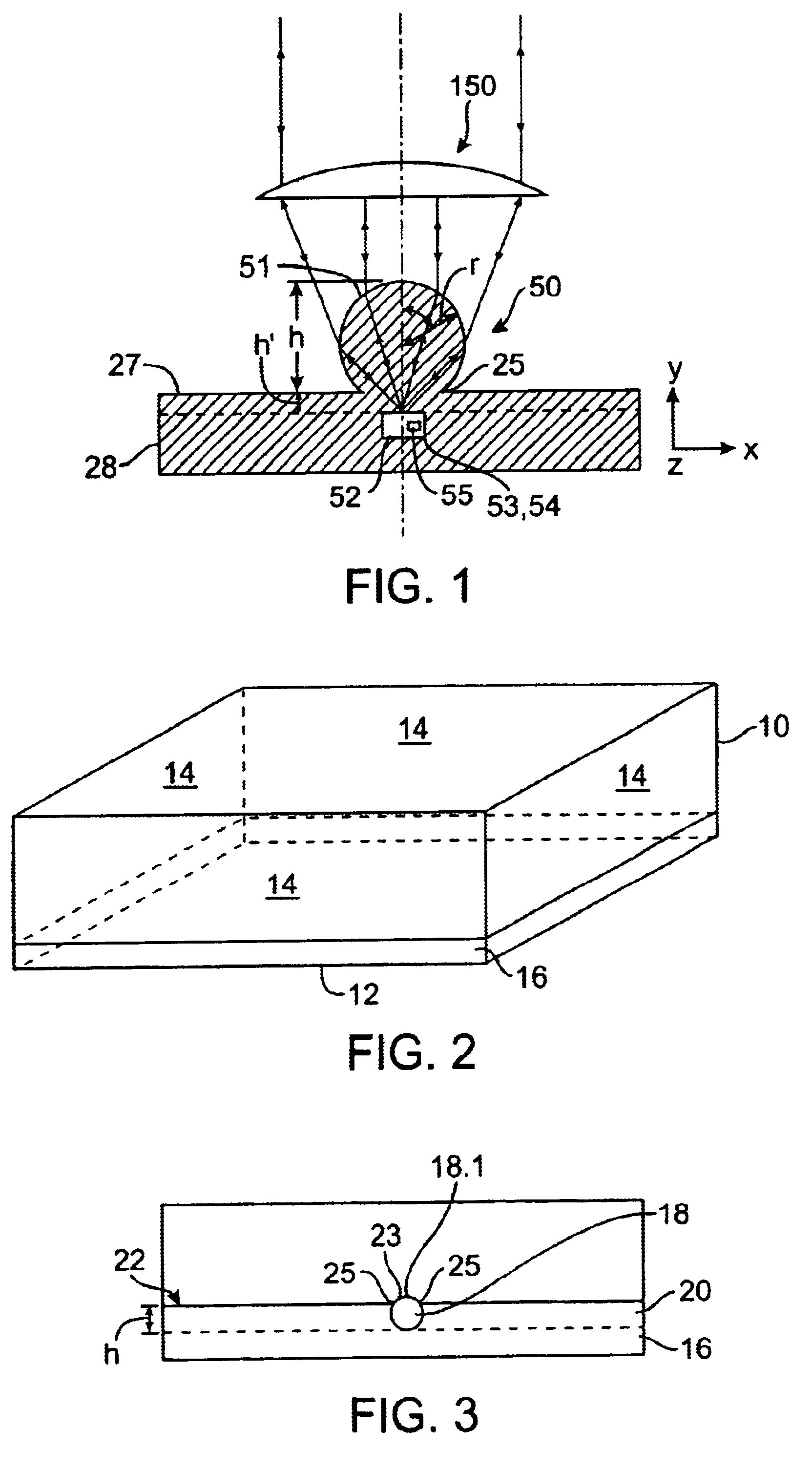
To create one exemplary mold of the meniscus type lens 400, a 395-micron radius micro sphere (“bead”) is used (Ruby ball lenses, Edmund industrial optics). This size is very close to the minimum size of about 360 microns needed to cover the SIL of Example 1.

In a large petri dish, the amount of silicon needed is poured; the thickness of the layer has to be exactly about 280 microns in order to achieve the correct height using this size bead. The silicon is poured in the center of the petri dish, and then spin the petri dish at 300 RPM until the silicon meets the borders of the petri dish.

The dish is placed in an oven for a few minutes (5-6 min) before putting in the bead. It's better to treat the bead with TMCS, and then to clean it with acetone before releasing it in the middle of the petri dish. The dish is then placed in the oven at 80° C. for 45 minutes.

There is no need for a layer of cured silicon under the bead, it can lie on the bottom of the petri dish because we just use the...

example 3

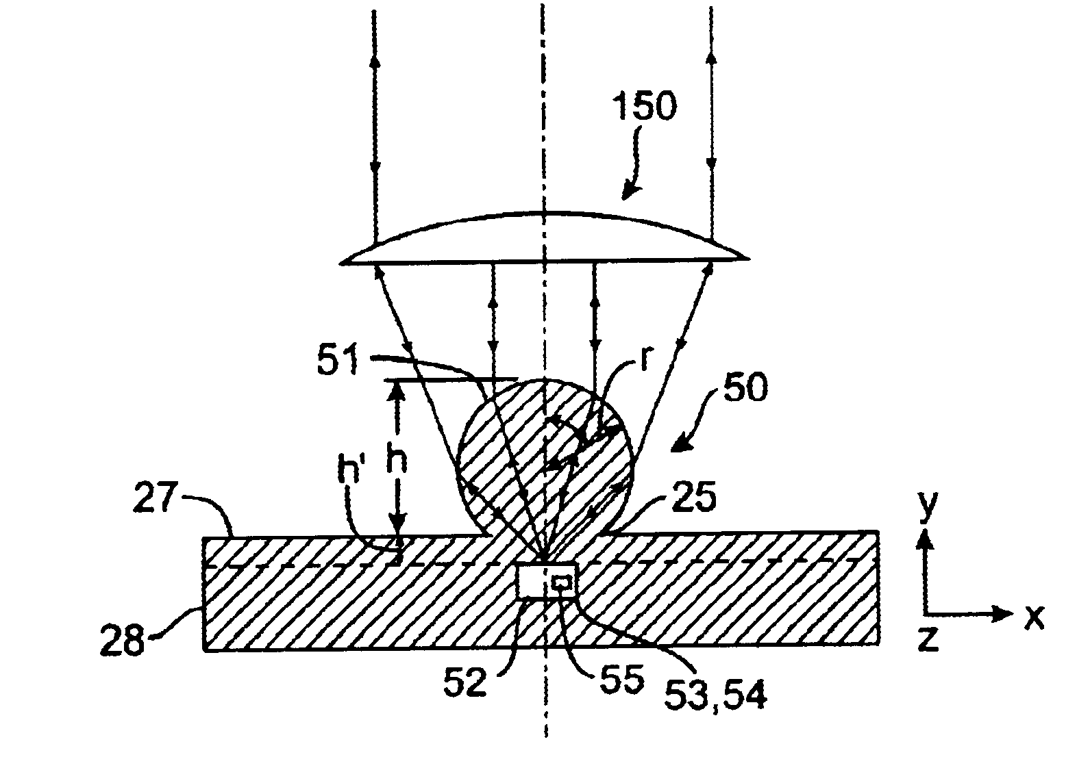
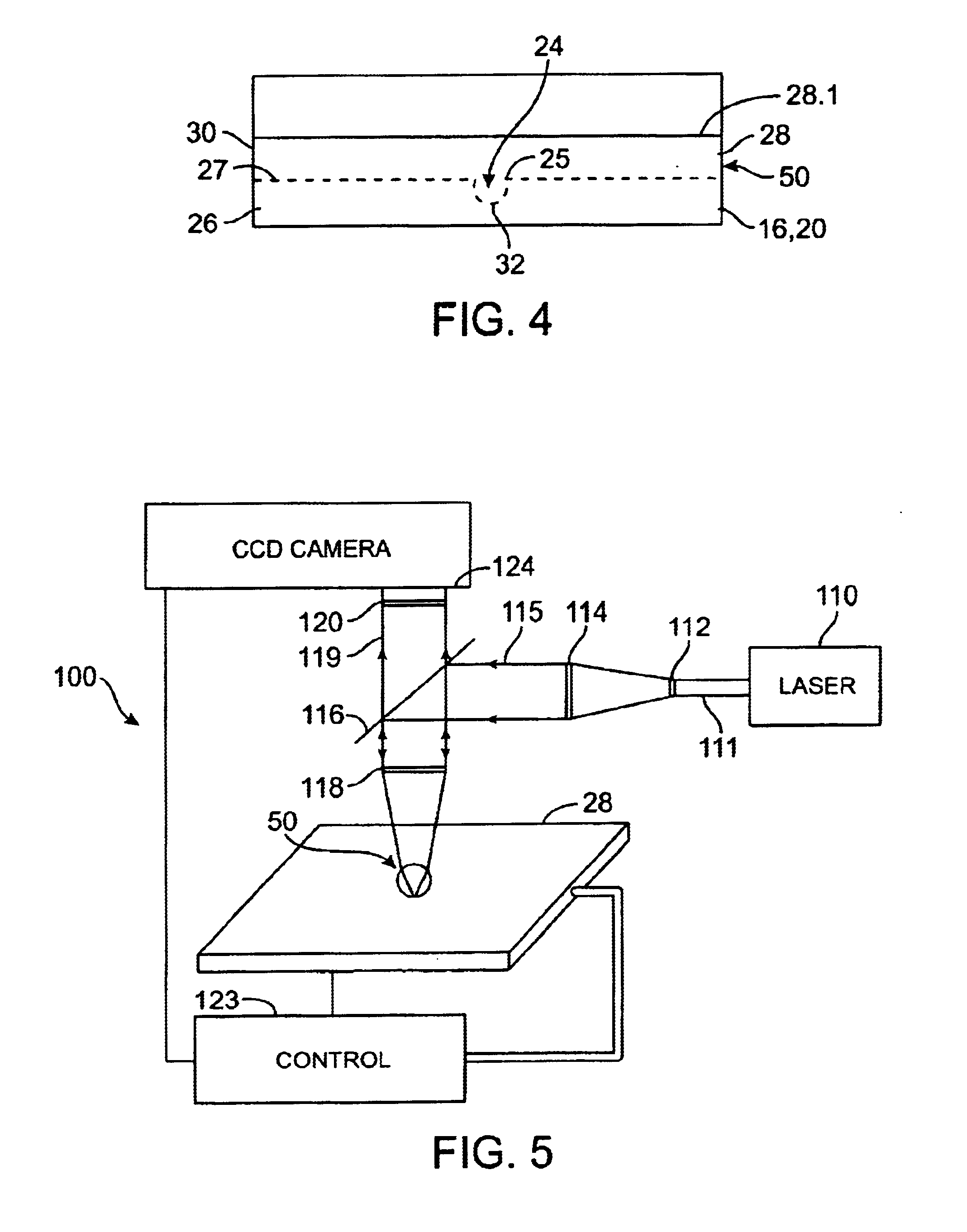
By using one of the solid immersion lens structures disclosed herein, the numerical aperture (NA) of the optical system may be increased to a value that is otherwise not obtainable using conventional lenses. FIG. 54 illustrates how the NA is increased using a solid immersion lens. An optical system 1400 is illustrated and in the exemplary embodiment, the system 1400 is a fluorescent microscope arrangement. The set of filters is chosen according to the dyes used in the different experiments (blue excitation and green emission). A laser 1410 is used to create the excitation and in this instance the laser 1410 is a blue laser having a wavelength of 488 nm and a beam diameter of 1 mm. A number of companies manufacture lasers having these characteristics and one exemplary laser 1410 is a Uniphase 2214-10 SL Argon Laser. The excitation may also be created by a blue LED 1220, e.g., Luxeon Star / C.

The filter set is selected in view of the excitation wavelength (coming from the laser 1410 or ...


PUM

PropertyMeasurementUnit
refractive indexaaaaaaaaaa
surface tensionaaaaaaaaaa

Abstract

Microfabricated lenses, e.g., solid immersion lens (SIL) structures, are provided along with techniques for constructing these lens structures, as well as selected applications of such lens structures.

Description

TECHNICAL FIELDThe present invention relates to microfabricated lenses, e.g., solid immersion lens (SIL) structures, and in particular to techniques for constructing these lens structures, as well as selected applications of such structures.BACKGROUND OF THE INVENTIONLenses are used to focus light in a variety of applications. For example, micro-structures, such as cells, are observed with light focused in microscopes. Lenses focus light by bending it according to the law of refraction. The law of refraction states that the change in angle (refraction) of a light ray as it passes from one material into another material is related to a material property called the index of refraction and the angle the light makes with the interface between the two materials. The index of refraction is a measure of the speed of light in the material. Lenses that are used in microscopes are specifically designed to bend light which has been reflected by small specimens so that their images appear magni...

Claims


Application Information

Patent Timeline
Patent Type & Authority Patents(United States)
IPC IPC(8): B29D11/00B29C39/02G02B21/00B29C39/24B29L11/00G02B3/00
CPCB01L3/502715B29D11/00365B29D11/00394G02B21/02G11B7/1374B01L3/502707B01L2300/0654B01L2300/0816Y10S425/808B01L2300/0887
Inventor QUAKE, STEPHEN R.GAMBIN, YANN
Owner CALIFORNIA INST OF TECH
Why Eureka
Try Eureka