Probe station having multiple enclosures

Inactive Publication Date: 2005-01-11
CASCADE MICROTECH
View PDF34 Cites 85 Cited by
  • Summary
  • Abstract
  • Description
  • Claims
  • Application Information

AI Technical Summary

Benefits of technology

The present invention satisfies the foregoing need by providing a probe station having respective inner and outer conductive shield enclosures insulated from each other, both enclosures at least partially enclosing the chuck assembly element which supports the test device, and also its associate

Problems solved by technology

However, as electrical test currents decrease, or as electrical test frequencies increase, the use of merely a single EMI shielding enclosure becomes less adequate.
However, if the shielding enclosure is exposed to EMI (such as electrostatic noise currents from its external environment), its ideal “quiet” condition is not achieved, resulting in unwanted spurious currents in the chuck assembly guard element and/or the supporting element for the test device.
The effect of such currents is particularly harmful to the operation of the guard element, where the spurious currents result in guard potential errors causing leakage curre

Method used


Image

  • Probe station having multiple enclosures
  • Probe station having multiple enclosures
  • Probe station having multiple enclosures

Examples


Embodiment Construction

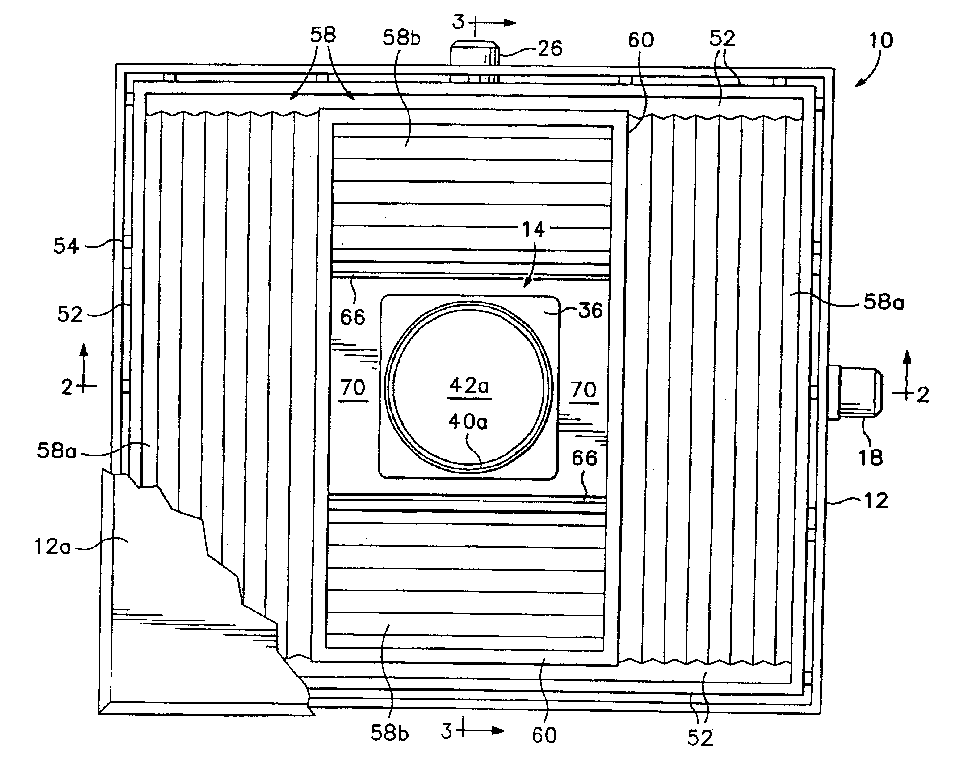
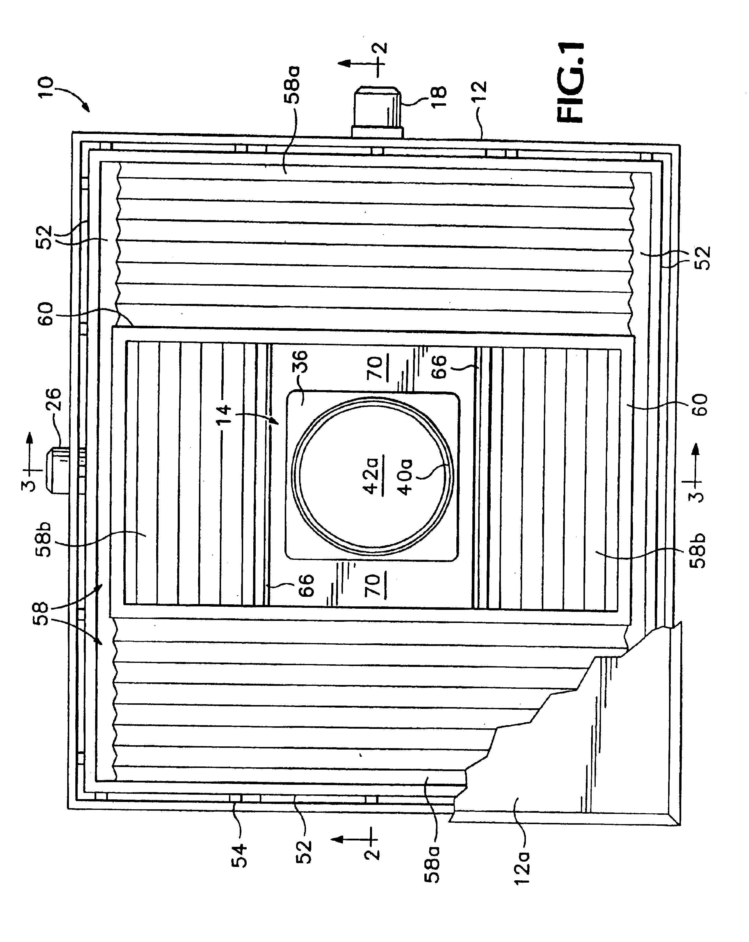
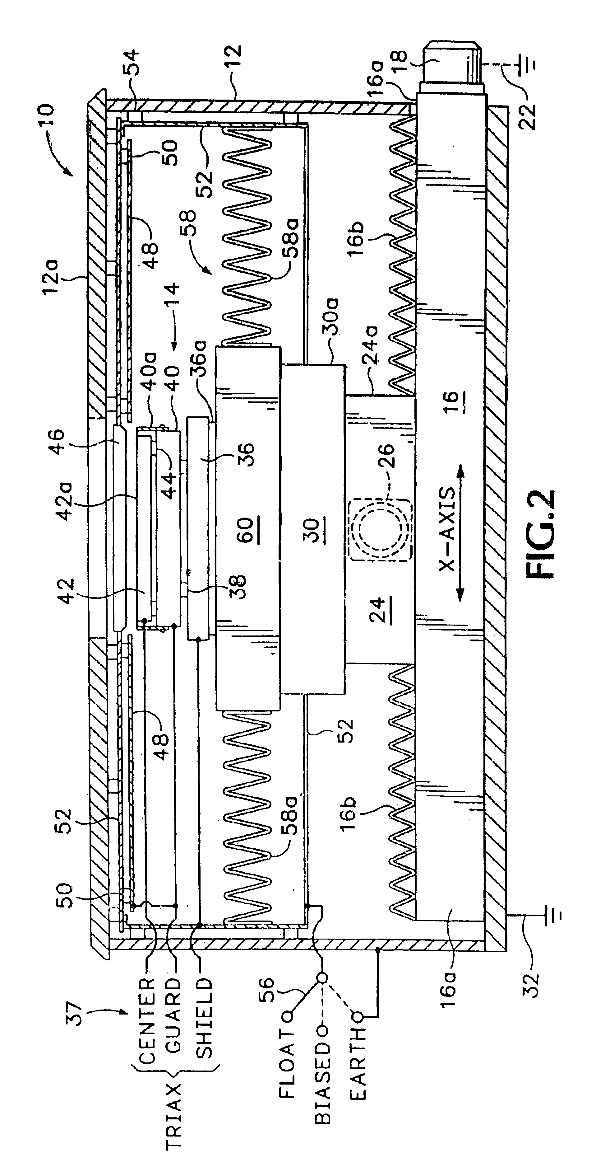
An exemplary embodiment of a probe station in accordance with the present invention, indicated generally as 10 in the figures, has an electrically conductive outer enclosure 12 including a conductive raisable hinged lid 12a electrically connected thereto. A chuck assembly 14 for supporting a test device is laterally positionable by a chuck positioner assembly having orthogonally arranged lateral X-axis and Y-axis positioners. A lateral X-axis positioner 16 has a laterally extending positioning screw (not shown) driven by an electric motor 18. The X-axis positioner 16 is partially enclosed by a conductive housing 16a, and optionally also by flexible pleated rubber boots 16b for accommodating positioning movements while preventing the entry and escape of dirt particles. The conductive housing 16a is insulated from the outer enclosure 12 by respective dielectric anodized coatings on both the exterior of the housing 16a and the interior of the enclosure 12, and is indirectly connected e...


PUM


Abstract

A probe station for probing a test device has a chuck element for supporting the test device. An electrically conductive outer shield enclosure at least partially encloses such chuck element to provide EMI shielding therefor. An electrically conductive inner shield enclosure is interposed between and insulated from the outer shield enclosure and the chuck element, and at least partially encloses the chuck element.

Description

BACKGROUND OF THE INVENTIONThe present invention relates to probe stations, commonly known as package or wafer probers, used manually, semiautomatically or fully automatically to test semiconductor devices. More particularly, the invention relates to such probe stations having EMI shielded enclosures for substantially enclosing the test devices, such as those probe stations shown in commonly-owned U.S. Pat. Nos. 5,266,889 and 5,457,398 which are hereby incorporated by reference.The probe stations shown in the foregoing patents are capable of performing both low-current and high-frequency measurements within a single shielded enclosure. However, as electrical test currents decrease, or as electrical test frequencies increase, the use of merely a single EMI shielding enclosure becomes less adequate. In the most sensitive of measurements, and particularly (although not necessarily) when guarding is employed for low current measurements as described in U.S. Pat. No. 5,457,398, the choic...

Claims


Application Information

Patent Timeline
IPC IPC(8): G01R1/02G01R1/04G01R31/28G01R31/26G01R1/06H01L21/66
CPCG01R1/04G01R1/18G01R31/2889G01R31/286G01R31/2886G01R31/2808G01R31/002
Inventor PETERS, RON A.HAYDEN, LEONARD A.HAWKINS, JEFFREY A.DOUGHERTY, R. MARK
Owner CASCADE MICROTECH
Why Eureka
Try Eureka