Beam expander

a beam expander and laser beam technology, applied in the direction of optics, instruments, optics, etc., can solve the problems of high intensity beam damage to optics, damage to optical systems, high intensity beam damage to high reflecting mirrors, etc., and achieve the effect of substantially increasing the life of the beam expander

Inactive Publication Date: 2005-01-11
PHOTONICS IND INTERN
View PDF5 Cites 19 Cited by
  • Summary
  • Abstract
  • Description
  • Claims
  • Application Information

AI Technical Summary

Benefits of technology

According to the invention, a high intensity laser beam delivery system is provided. In another aspect of the invention, a beam expander for use in high intensity laser beam delivery apparatus is provided and a method of expanding the beam size of a high intensity beam is provided. In the use of high intensity beams, especially UV beams, the high intensity beams can damage optics that are used to direct and focus the high intensity beam on the work surface. Thus, the high intensity beams can damage the mirrors, coatings and lenses used in optical systems. As a result, it is important to reduce the intensity of the beam prior to its incidenting on the optics.
After a period of time, the high intensity beam will damage the coating of high reflecting mirror. At such time, the mirror will be moved preferably rotated about a preselected axis to bring a different position on the mirror in the path of the high intensity beam. Desirably, the highly reflecting mirror will be rotated about an axis that will not change the path of the reflected beam. The rotation results in a new position on the mirror being placed in the path of the high intensity beam. Preferably, the beam will then be reflected along the same path as it was prior to rotation of the mirror. The mirror can be rotated numerous times around the circumference of the mirror if the mirror curvature is spherical until there are no points around the circumference of the mirror that have not been damaged. If the mirror is convex cylindrical shape, the mirror can be moved along cylindrical axis or rotated around the circumference numerous times. Thus, the longevity of the beam expander has been substantially increased.

Problems solved by technology

In the use of high intensity beams, especially UV beams, the high intensity beams can damage optics that are used to direct and focus the high intensity beam on the work surface.
Thus, the high intensity beams can damage the mirrors, coatings and lenses used in optical systems.
After a period of time, the high intensity beam will damage the coating of high reflecting mirror.

Method used


Image

  • Beam expander
  • Beam expander
  • Beam expander

Examples


example

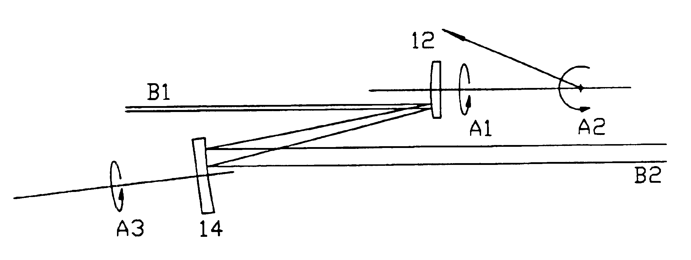
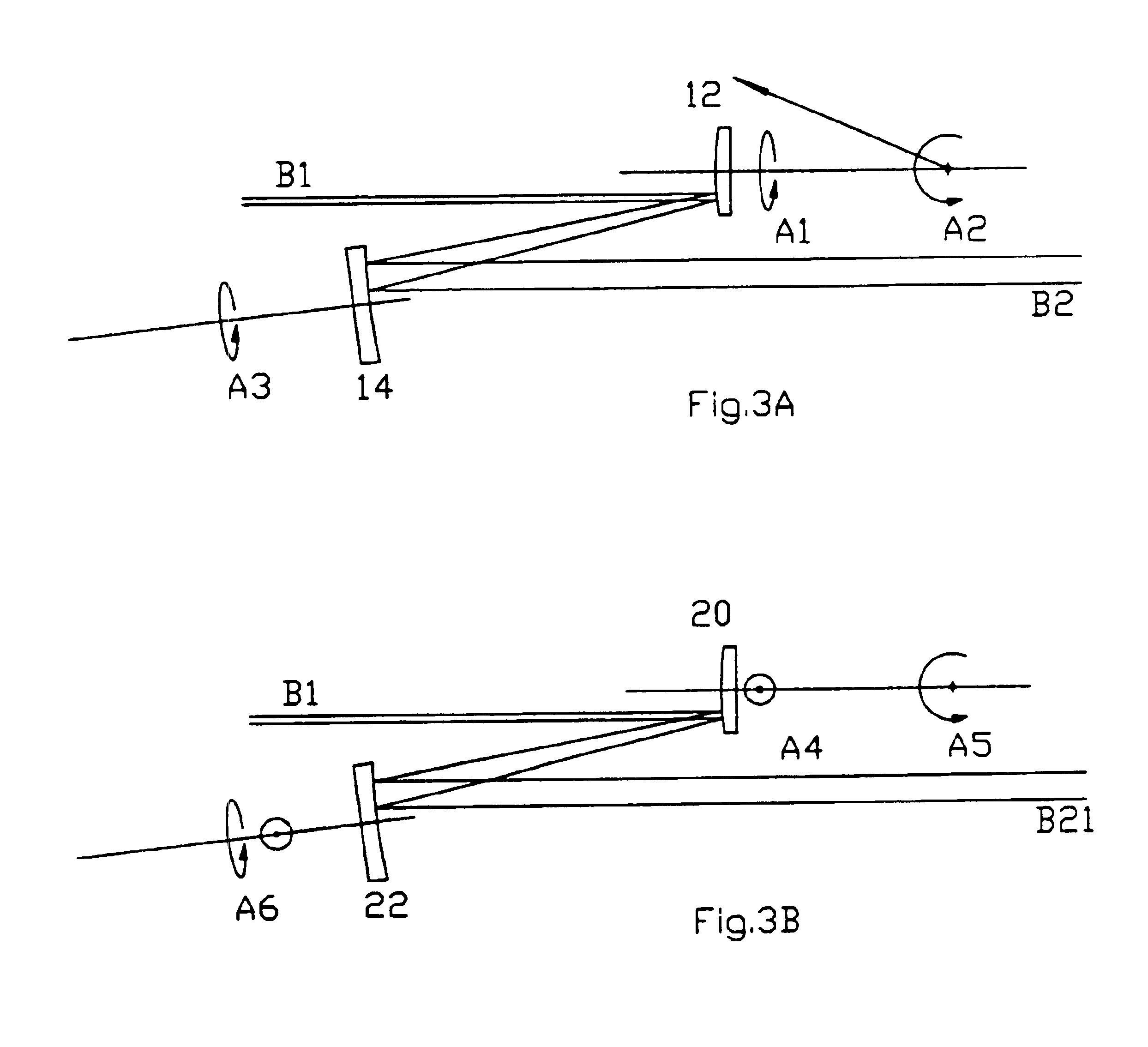
A beam expander as shown in FIG. 3A was constructed. B1 UV beam is 10 watts UV 355 nm laser beam with beam diameter of about 1 mm. The coating of the mirror 12 coated from Spectrum Thim Film, Bohemia, N.Y., lasted about 150 hours before it is substantially deteriorated or damaged. After 150 hours, the mirror 12 was rotated to a new position where it lasted another about 150 hours. There are at least 200 available points for the mirror 12 to rotate, approximate lifetime for the mirror 12 is about 30,000 hours as compared to prior art of about 150 hours.

Referring to FIG. 5, a beam expander for use in a high intensity laser beam delivery apparatus is provided. As in FIG. 3, a high intensity beam B1 is directed to a concave or convex mirror 12 which has been rotatably mounted in the path of high intensity beam B1. The mirror 12 has at least one axis of rotation, preferably two axes A1 and A2 of rotation. Desirably, the axes of rotation pass through the origin of curvature of the mirror....


PUM


Abstract

A laser beam includes a concave or convex mirror which is reflective for wavelength of the high intensity beam. The reflective mirror is located along a preselected path of a high intensity laser beam so that the high intensity laser beam intersects the mirror at a first position. A beam collimator is located in the path of the high intensity beam reflected by the concave or convex mirror. The concave or convex mirror is movably mounted desirably rotatably mounted in the path of the high intensity beam. Desirably the mirror is rotated about a preselected axis. Desirably, the axis is selected so that when the mirror is rotated to a new position, the high intensity beam will be reflected along the same path to the collimator as it was prior to any rotation.

Description

BACKGROUND OF THE INVENTION1. Field of the InventionThe subject invention relates to a high intensity laser beam delivery system, a beam expander for use in a high intensity laser beam delivery system and a method for expanding the beam diameter of a high intensity beam.2. Background and Related ArtHigh intensity laser beams are now in use in the art. Such beams include UV beam such as third and fourth harmonic of Nd:YAG, Nd:YVO4 and Nd:YLF UV beams. See U.S. Pat. Nos. 5,898,717 (YIN) and 6,061,370 (YIN). High intensity beams particular UV beams can damage the coatings, lenses and mirrors used to direct and focus the high intensity beam to a desired location or work surface.Beam expanders have been used in the art for a variety of purposes. For example, beam expanders have been used to increase the beam diameter of a high intensity beam to reduce damage to system components. They have also been used to expand the beam so it can then be focused to smaller spot size. However, such pri...

Claims


Application Information

Patent Timeline
Patent Type & Authority Patents(United States)
IPC IPC(8): G02B27/30
CPCG02B27/30
Inventor YIN, YUSONGZHAO, XIAOJIEZHAO, JING
Owner PHOTONICS IND INTERN
Why Eureka
Try Eureka