

Automatic transmission
a transmission and automatic technology, applied in the direction of rotary clutches, gearings, fluid couplings, etc., can solve the problems of increased leakage at the required temperature range, increased cost, and cast-in-place fluid feed flanges, so as to reduce the number of components required, reduce the size of the unit, and increase the strength
- Summary
- Abstract
- Description
- Claims
- Application Information
AI Technical Summary
Benefits of technology
Problems solved by technology
Method used
Image

Examples
Embodiment Construction
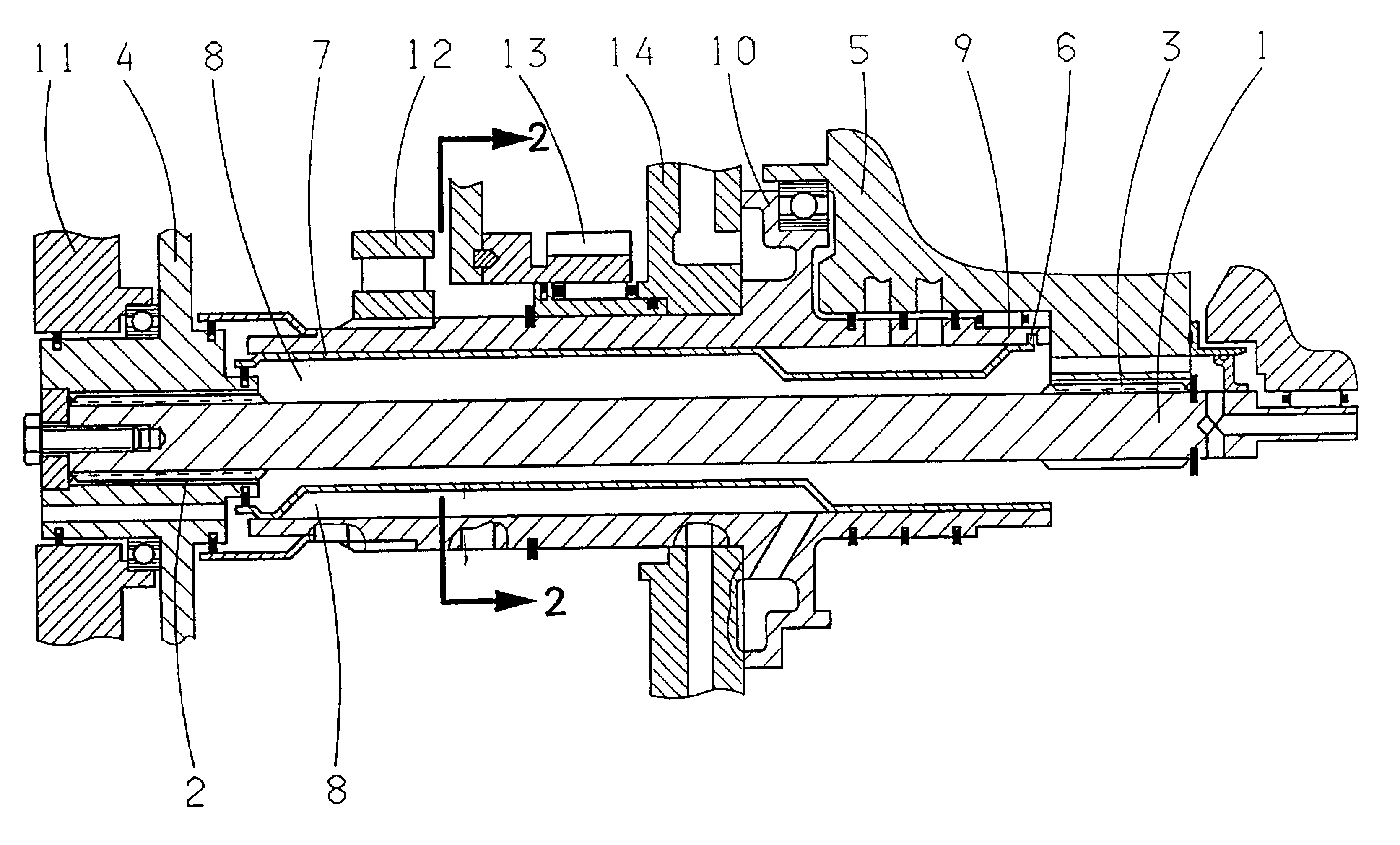
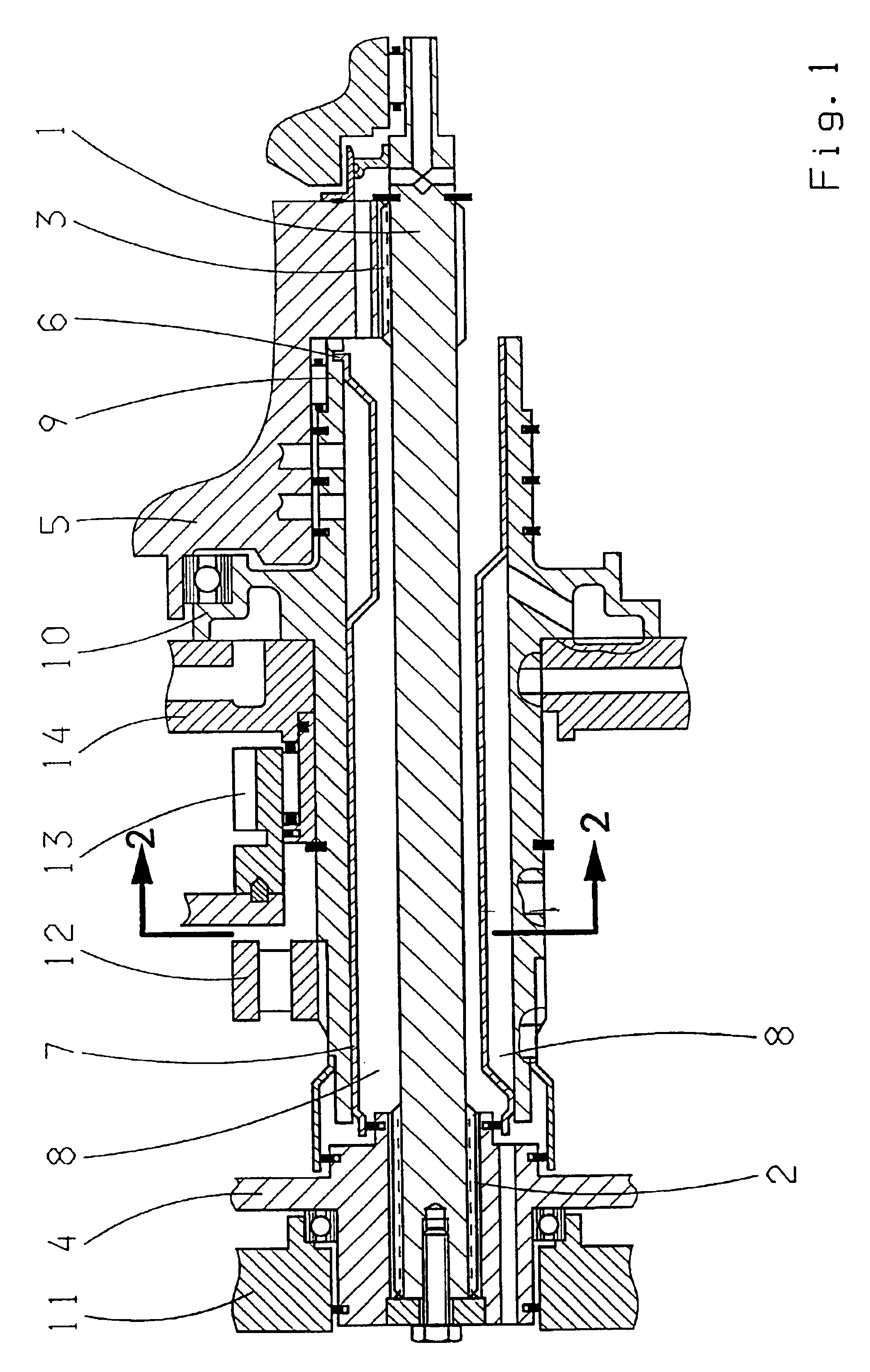
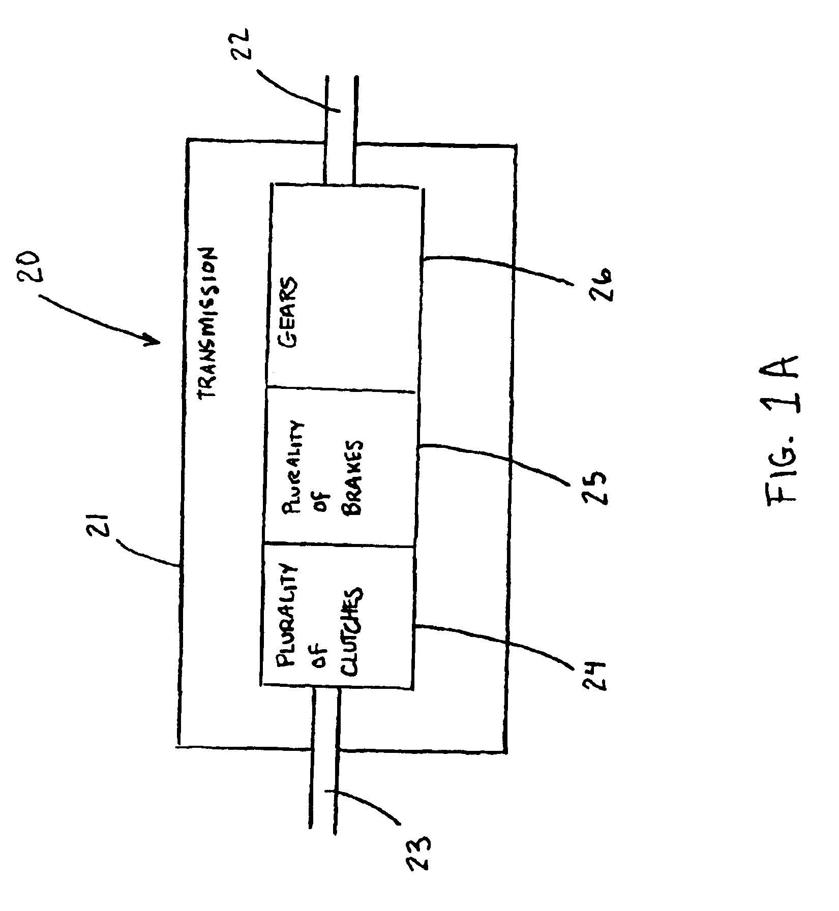
The automatic transmission 20, illustrated in FIGS. 1 and 1A, is equipped with a torque-controlling shaft 1, hereinafter referred to as the turbine shaft, which is in a working connection with a turbine 4 and a clutch body 5 via (first and second) slaving teeth 2 and 3. The turbine shaft is designed as a solid shaft and has neither cross bores nor grooves between the slaving teeth 2 and 3. The central feed of fluid to a plurality of clutches 24 and brakes 25 of the automatic transmission is accomplished via a stator shaft 9 and an insert 6. A sealing element, which is not illustrated here, is located between the turbine 4 and the insert 6. The insert contains the fluid channels 8 and the gates 7; which ensure a sealing between the channels and against the outside. The stator shaft 9 is equipped with a flange 10; which serves as a bearing for the clutch body 5. A converter cover 11 is situated on the turbine 4. A freewheel clutch 12, a power take off 13, and a control unit 14 are con...
PUM
 Abstract
Description
Claims
Application Information