Spinal vertebral implant and methods of insertion

a technology of spinal vertebrae and implants, which is applied in the field of spinal vertebrae implants, can solve the problems of reduced fusion or lack, extreme pain to patients suffering from such injuries, and the space used in the cage is not used, so as to prevent the implant from being placed, stimulate bone growth, and encourage greater fusion

Inactive Publication Date: 2005-01-18
BRYAN DONALD W
View PDF43 Cites 99 Cited by
  • Summary
  • Abstract
  • Description
  • Claims
  • Application Information

AI Technical Summary

Benefits of technology

e stimulated bone growth. It is an advantage of the present invention that the use of bone allows not only the bone fragments, but the bone implant itself to become incorporated as part of the final fused spine.
Further, because the implant is one solid piece, it is strong enough to be driven in and maintained between vertebrae without structural failure. Finally, bone will incorporate naturally into the bone fusion, whereas metal will not.
With reference now to FIGS. 2 and 3, examples of placement of implant 10 will now be described. As shown, it is preferred that first and second implants 10a, 10b be placed between upper and lower vertebrae 30, 32. Side portions 31, 33 of respective upper and lower vertebrae 30, 32 are partially cut away in FIGS. 2, 5b and 5c (see hatching), in order to completely illustrate the placement of implant 10 between the vertebrae.
It is preferred to drive implant 10 between adjacent vertebrae 30, 32, such that implant 10 achieves a desired level of distraction of the anterior portions of vertebrae 30, 32. By driving nose section 14 between the adjacent vertebrae 30, 32, implant 10 is forced between the vertebrae and thereby accomplishes a tight fit therebetween, thereby fostering and encouraging gre

Problems solved by technology

Such injuries are common in the lumbar vertebrae, for example, and can cause extreme pain to a patient suffering from such injuries.
Thus, the space used by the cage is not used to fo

Method used


Image

  • Spinal vertebral implant and methods of insertion
  • Spinal vertebral implant and methods of insertion
  • Spinal vertebral implant and methods of insertion

Examples


example 1

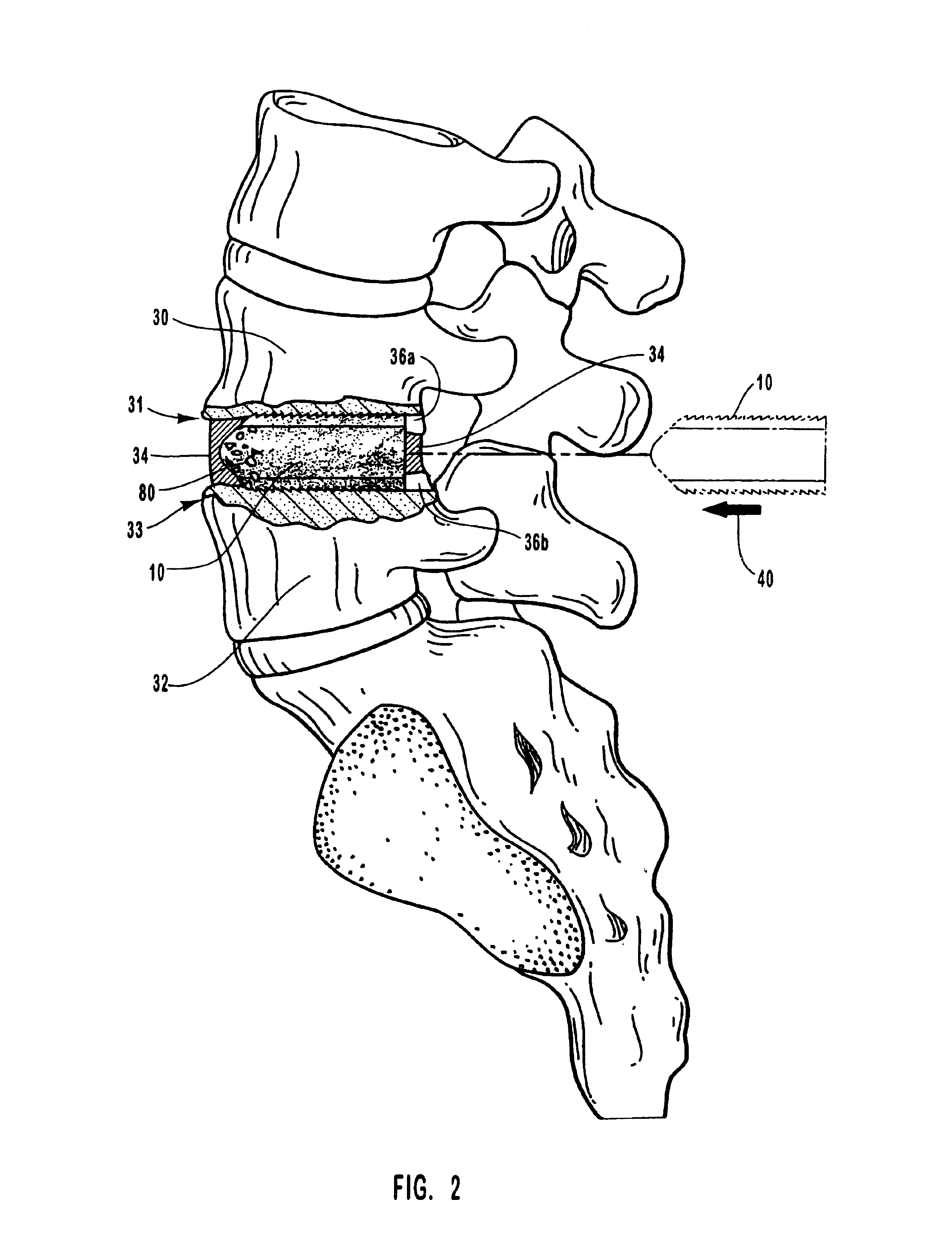
The following procedure was effectively performed on a patient. A midline incision was made and the patient's spine was exposed by subperiosal dissection. Decompression was begun with partial facet joint excision. The capsule of the facet joint was removed with electric cautery and periostial elevator. Since virtually all removed bone is preferably used as graft, extra time was taken to meticulously remove attached soft tissue. The upper facet was cut transversally with an osteotome and removed. Initially, the spinous processes were left intact to facilitate distraction with the laminus spreader.

The interspinous ligament was removed and a laminae spreader was inserted. Cartilage and other soft tissue from the facet joint were removed with a cob elevator and an adison rongeur. The inferior facet was excised, saving the small bits of bone for later grafting. The disk space was radically excised to the outer annulus. The end-plates were vigorously curetted to bone. A cottonoid was plac...


PUM


Abstract

A spinal vertebral implant includes a substantially rectangular shaped base section made from a solid piece of bone. A nose section extends integrally from the substantially rectangularly shaped base section and preferably has a generally tapering shape to foster entry between adjacent vertebrae. The nose section tapers distally and inwardly from the base section to form a generally pointed or rounded distal tip portion and comprises a solid piece of bone. Serrated sides assist the implant in gripping adjacent upper and lower vertebrae and in being maintained therebetween. The serrated sides are angled in a manner that encourages the implant to be placed between the vertebrae and locked therebetween upon such placement. First and second implants may be placed into respective left and right sides of an intervertebral space. A method for placing one or more implants between the adjacent vertebrae comprises forming a slot configured to receive an implant and inserting the implant into the slot. Each slot is preferably formed from an upper slot portion and a lower slot portion in the posterior portion of adjacent upper and lower vertebrae, respectively. Instruments for performing the method include osteotomes, impactors, and spacers.

Description

BACKGROUND OF THE INVENTION1. The Field of the InventionThis invention relates to spinal vertebral implants and methods and instruments for inserting the implants between spinal vertebrae in order to achieve spinal fusion.2. The Prior State of the ArtWhen tissues between spinal vertebrae, also known as intervertebral disks, become herniated or otherwise injured, the disks can compress against nerves associated with a particular location on a spinal column. Such injuries are common in the lumbar vertebrae, for example, and can cause extreme pain to a patient suffering from such injuries.One treatment common among medical providers to treat such injured intervertebral disks is a spinal fusion. In typical spinal fusion procedures, a portion of a vertebral disk or the entire vertebral disk is removed from between adjacent upper and lower vertebrae and the upper and lower vertebrae are fused to form a single spinal structure. The fusion of the vertebrae can alleviate the pain and discomf...

Claims


Application Information

Patent Timeline
IPC IPC(8): A61B17/16A61F2/44A61F2/46A61B17/02A61F2/30A61F2/00A61F2/28
CPCA61B17/025A61B17/1671A61F2/28A61F2/4455A61F2/4611Y10S606/914A61B2017/0256A61F2/442A61F2002/2835A61F2002/2839A61F2002/30131A61F2002/30904A61F2002/448A61F2002/449A61F2002/4602A61F2002/4623A61F2002/4649A61F2002/4681A61F2230/0013Y10S606/909A61B17/1604A61F2/4601A61F2/4603
Inventor BRYAN, DONALD W.
Owner BRYAN DONALD W
Why Eureka
Try Eureka