Intervertebral implant

Inactive Publication Date: 2005-01-18
SYNTHES USA
View PDF16 Cites 82 Cited by
  • Summary
  • Abstract
  • Description
  • Claims
  • Application Information

AI Technical Summary

Benefits of technology

The implant is preferably provided with a convex top and/or bottom surface which matches the concave shape of the natural end plates of the vertebrae, to achieve better contact between the implant and the end plates.
The outer surface jacketing the intervertebral implant is preferably provided with one or several perforations primarily for the purpose of engaging an instrument for manipulating the implant. The perforations may be located both on the anterior side and in th

Problems solved by technology

The drawback of this earlier implant lies in the fact that the basic body of the implant consists of typical nonceramic and hence nonresorbable materials.
The drawback of that earlier implant concept lies, on the one hand, in its low pressure resistance attributable to

Method used


Image

  • Intervertebral implant
  • Intervertebral implant

Examples


Embodiment Construction

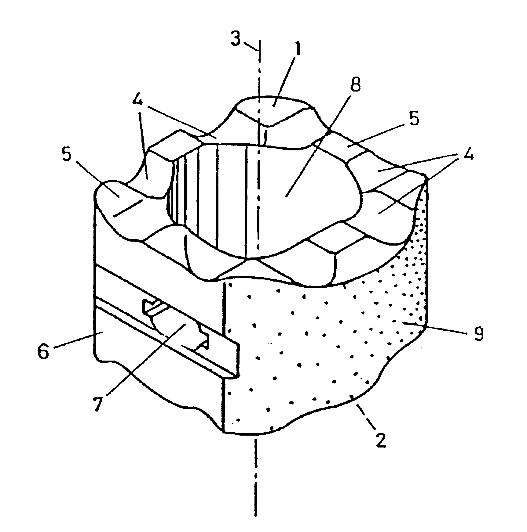
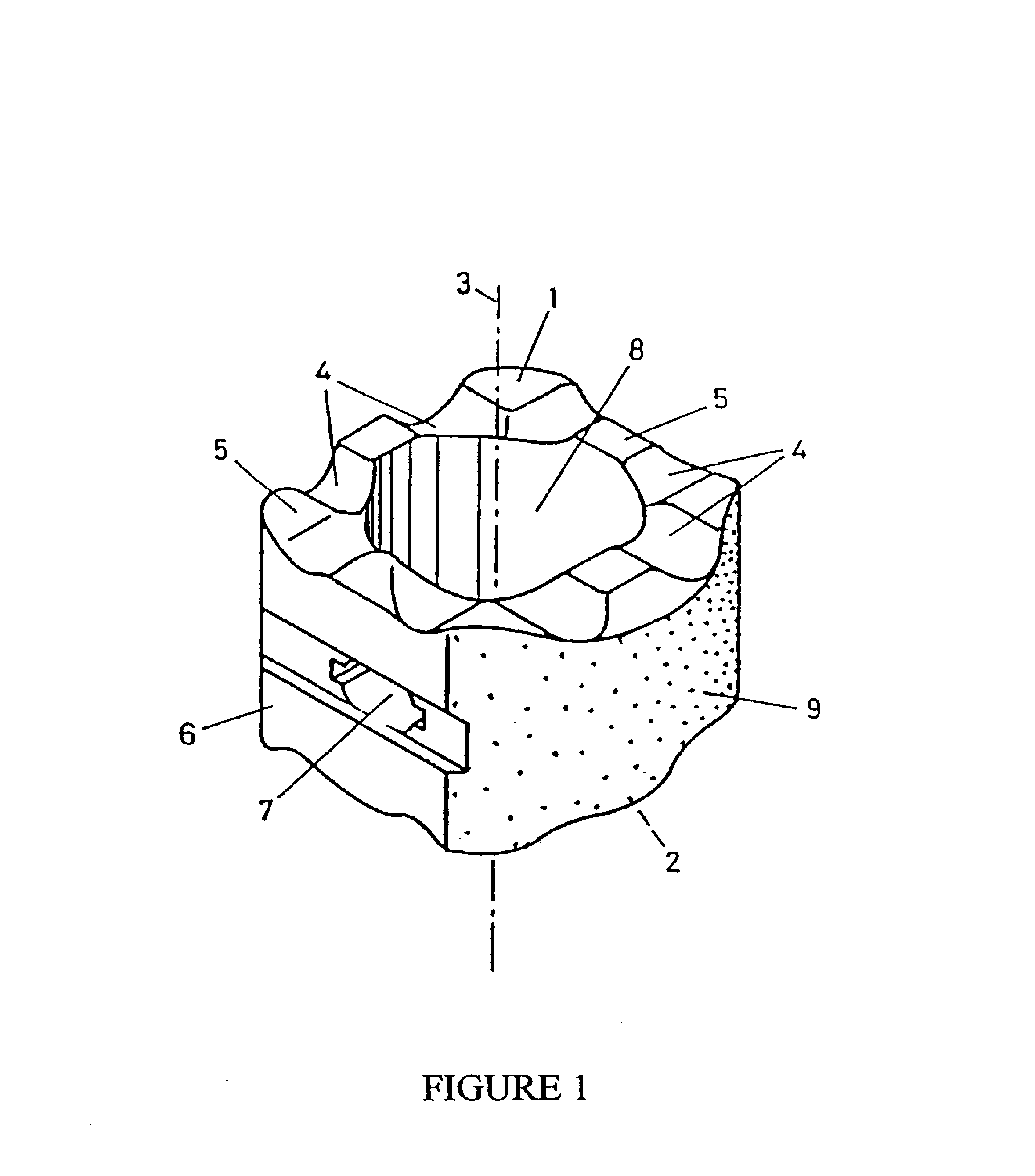
The intervertebral implant illustrated in FIG. 1 consists essentially of a hollow cylinder with an inner space 8, a longitudinal axis 3, a top surface 1 and a bottom surface 2. The intervertebral implant is essentially produced from a polycrystalline ceramic material. The ceramic material has a porosity of 5 vol. %, the pores are filled with air. The width of the pores is less than 100 μm and preferably less than 50 μm. The foreign-phase content of the ceramic material is 1.5% by weight. The pressure resistance of the ceramic material is 500 Mpa.

The top and bottom surfaces 1, 2 serve to provide bone contact with the surface plates of two vertebrae and are configured accordingly. The wall thickness of the intervertebral implant is 7 mm, the density of the ceramic material is 3.2. The top surface 1 and the bottom surface 2 are not planar but are provided with a number of grooves 4 and ridges 5 extending in a perpendicular (i.e. radial) direction relative to the longitudinal axis 3.

The...


PUM

PropertyMeasurementUnit
Lengthaaaaaaaaaa
Lengthaaaaaaaaaa
Percent by massaaaaaaaaaa

Abstract

The present invention relates to an intervertebral implant for fusion of vertebrae. The implant has top and bottom surfaces configured and dimensioned to contact end plates of the vertebrae and a jacket forming a side surface of the implant and having a three-dimensional texture for promoting initial stability. The implant is made of a porous ceramic material. The implant according to this invention is characterized in that upon primary fusion during the resorption process, it equalizes the distance (corresponding to intervertebral disk height) between two vertebrae while providing adequate fusion and is resorbed by the body after a certain amount of time.

Description

FIELD OF THE INVENTIONThis invention relates to an intervertebral implant for use in spinal fusion.BACKGROUND OF THE INVENTIONIntervertebral implants of this type are inserted when, after removal of the intervertebral disk between two vertebrae (especially in the lumbar section of the vertebral column), the vertebrae are to be fused. One or two such implants are used in each intervertebral space.In EP-B 346.269, FUHRMANN ET AL already describe an intervertebral implant whose outside front, end and lateral surfaces are coated with a layer of hydroxyl apatite or a ceramic HIP material. The drawback of this earlier implant lies in the fact that the basic body of the implant consists of typical nonceramic and hence nonresorbable materials.In U.S. Pat. No. 5,306,303, LYNCH describes an intervertebral implant which consists entirely of a porous ceramic material. The drawback of that earlier implant concept lies, on the one hand, in its low pressure resistance attributable to the relativel...

Claims


Application Information

Patent Timeline
IPC IPC(8): A61F2/44A61L27/00A61L27/10A61L27/56A61F2/30A61F2/00A61F2/02A61F2/28A61F2/46
CPCA61F2/4465A61F2/447A61L27/10A61L27/56A61F2/30771Y10S606/912A61F2/4611A61F2002/2835A61F2002/30062A61F2002/3023A61F2002/30235A61F2002/30271A61F2002/30772A61F2002/3082A61F2002/30828A61F2002/30831A61F2002/30892A61F2002/4475A61F2210/0004A61F2230/0069A61F2230/0082A61L2430/38Y10S606/908A61F2/442A61F2002/30261A61F2002/30593
Inventor WEBB, JOHNHAFELI-KNOTHE, INGA MARENHAFELI, THOMASBENOIT, ALFRED
Owner SYNTHES USA
Why Eureka
Try Eureka