Oxide-ion conductor and use thereof

a gallate oxide and conductor technology, applied in the field of rare earth gallate oxideion conductors, can solve the problems that known conductors cannot be used as the material of solid oxide fuel cells, cannot be used practically as oxide-ion conductors, etc., and achieve the effect of improving the oxide-ion conductivity and the oxide-ion conductivity

Inactive Publication Date: 2005-01-18
MITSUBISHI MATERIALS CORP +2
View PDF1 Cites 12 Cited by
  • Summary
  • Abstract
  • Description
  • Claims
  • Application Information

AI Technical Summary

Benefits of technology

The inventors have made a study to find materials which would exhibit still higher oxide-ion conductivity. As a result, the inventors have discovered that the addition of a small amount of a transition me

Problems solved by technology

As discussed in the foregoing, although oxide-ion conductors having higher oxide-ion conductivity than stabilized zirconia are known, such known conductors cannot suitably be used as the material of an electrolyte in solid oxide fuel cells, oxygen sensors and so forth, because of insufficiency in heat resistance and/or a large reduction in the ion transfere

Method used


Image

  • Oxide-ion conductor and use thereof
  • Oxide-ion conductor and use thereof
  • Oxide-ion conductor and use thereof

Examples


example 1

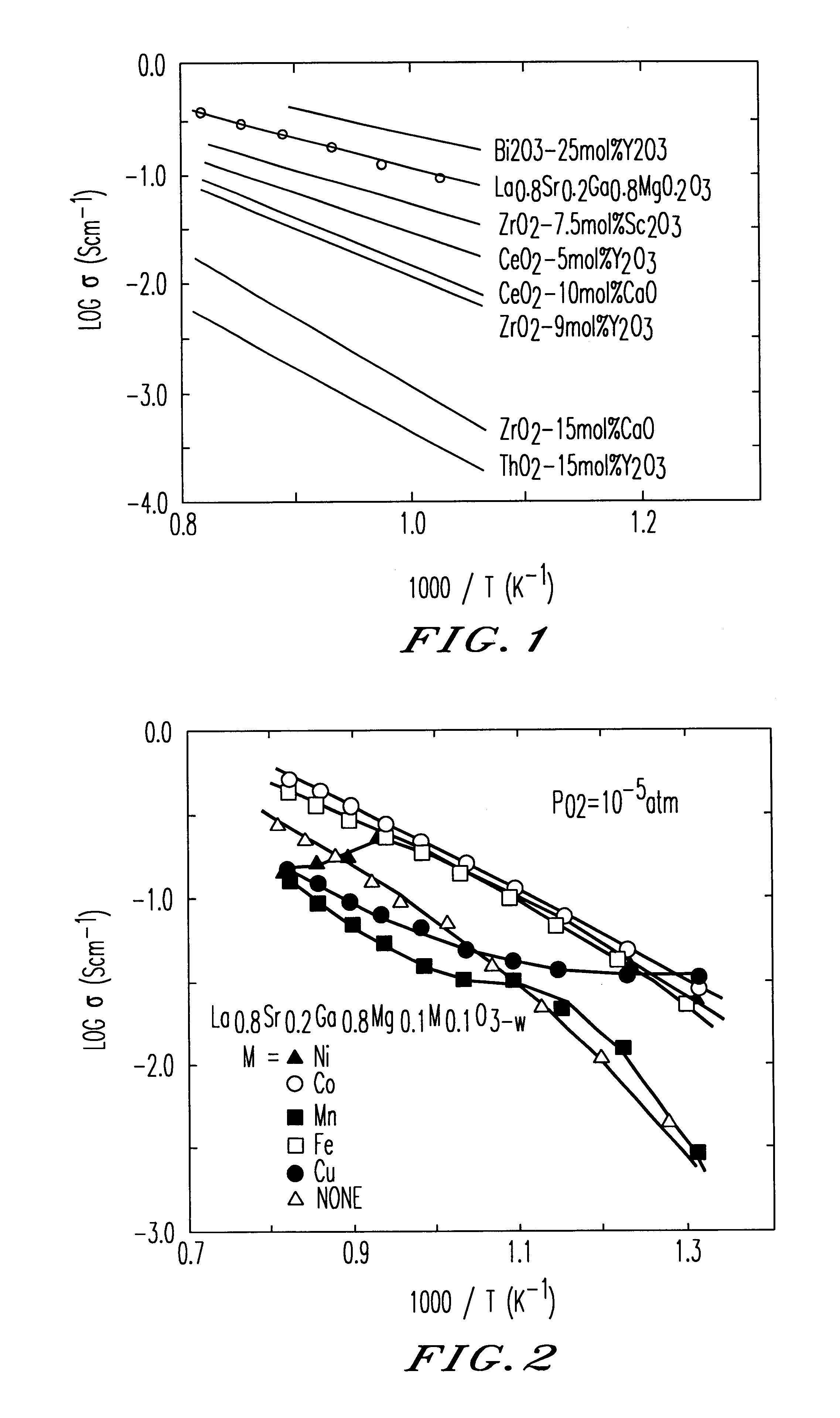
Powders were prepared from La2O3, SrCO3, Ga2O3, MgO and one or more transition metal oxides selected from CoO, Fe2O3, Ni2O3, CuO and MnO2. These powders were mixed to provide a composition expressed by La0.8Sr0.2Ga0.8Mg0.1M0.1O3−w (“M” being a transition metal). After sufficient blending, the mixture was pre-heated at 1000° C. for 6 hours. The pre-heated mixture was then crushed and compression-formed into disks 0.5 mm thick and 15 mm diameter, by means of a isostatic press, and the disks thus formed were sintered by being heated at 1500° C. for 6 hours. The crystal structures of the sintered disks were examined by means of X-ray diffraction and confirmed to have the perovskite structure.

Electrical conductivity of the sintered body was examined as follows. Rectangular parallelepiped test pieces were cut out from the disk-shaped sintered bodies. After application of a platinum paste as electrodes, platinum wires were connected to each test piece, followed by heating at temperatures v...

example 2

Test pieces of oxide-ion conductor was produced from a sintered body of La0.8Sr0.2Ga0.8Mg0.115CO0.085O3−w in the same manner as Example 1 and were subjected to measurement of electrical conductivity at varying temperature under a fixed oxygen partial pressure of 10−5 atm. The results of the measurement (Arrhenius plot of conductivity) are shown in FIG. 11.

example 3

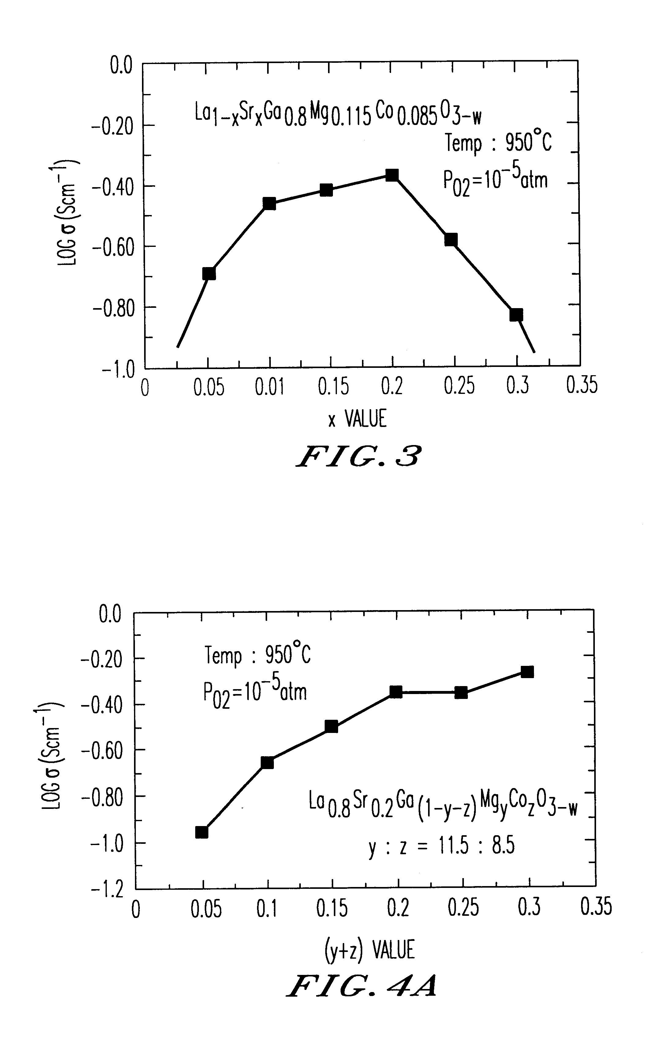
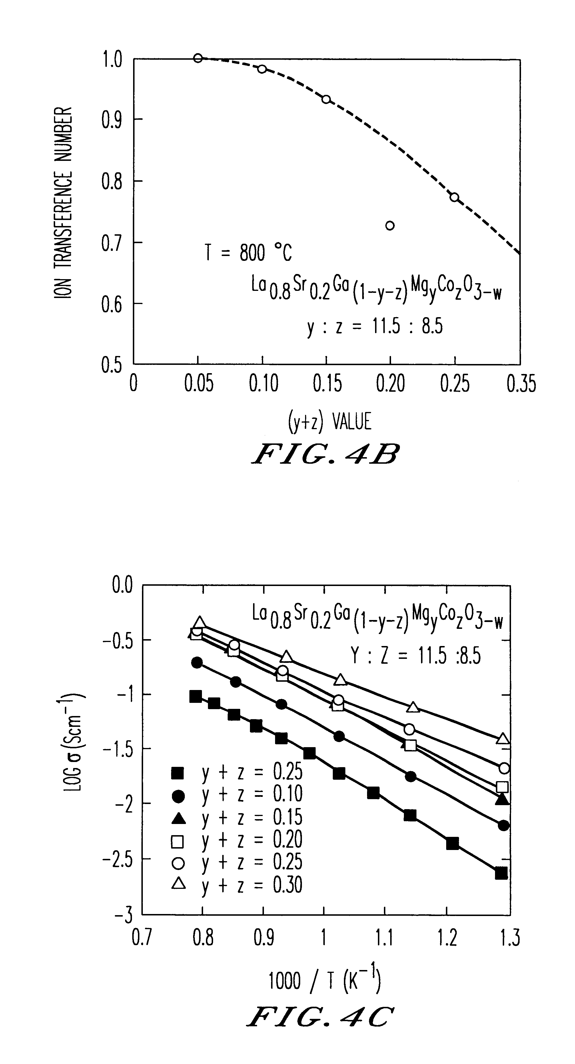
Test pieces of oxide-ion conductor were produced from a sintered body of La1−xSrxGa0.8Mg0.115Co0.085O3−w (x=0.1, 0.15, 0.2, 0.25 or 0.3) in the same way as Example 1 and were subjected to measurement of electrical conductivity at varying temperature under a fixed oxygen partial pressure or at a fixed temperature under varying oxygen partial pressure. FIG. 3 shows the relationship between the value of “x” and the electrical conductivity as observed at 950° C. The Arrhenius plot of conductivity (oxygen partial pressure 10−5 atm) and the oxygen-partial-pressure dependence of the electrical conductivity (at 950° C.) are respectively shown in FIGS. 12A and 12B. It will be noted that the oxygen-partial-pressure dependence of conductivity varies according to the “x” value.


PUM

PropertyMeasurementUnit
Electrical conductivityaaaaaaaaaa
Electrical conductoraaaaaaaaaa
Thermal resistanceaaaaaaaaaa

Abstract

An oxide-ion conductor has the formula Ln1−xAxGa1−y−xB1YB2z oxide, wherein Ln is at least one element selected from the group consisting of La, Ce, Pr, Nd and Sm; A is at least one element selected from the group consisting of Sr, Ca and Ba; B1 is at least one element selected from the group consisting of Mg, Al and In; B2 is at least one element selected from the group consisting of Co, Fe, Ni and Cu; x is 0.05 to 0.3; y is 0 to 0.29; z is 0.01 to 0.3; and y+z is 0.025 to 0.3. The oxide-ion conductor exhibits higher oxide-ion conductivity than stabilized zirconia, excellent heat resistance and also high ion conductivity even at low temperatures, as well as exhibiting low oxygen-partial-pressure dependence of ion conductivity.

Description

BACKGROUND OF THE INVENTION1. Field of the InventionThe present invention relates to a novel rare earth gallate oxide-ion conductor, having a perovskite structure. The oxide-ion conductor of the present invention exhibits very high oxide-ion conductivity or oxide-ion mixed conductivity without being substantially affected by oxygen partial pressure, and can effectively be incorporated in an electrolyte of a fuel cell, an air electrode of a fuel cell, a gas sensor such as oxygen sensor, an oxygen separating film such as electrochemical oxygen pump, a gas separator membrane, and so forth.2. Discussion of the BackgroundAn oxide-ion conductor owes its electrical conductivity mainly to the mobility of oxide ions (O2−), without substantially relying on conductivity by electrons. In general, such an oxide-ion conductor is made of a metal oxide that is doped with another metal, so as to generate O2− vacancies. Attempts have been made to put such oxide-ion conductors to use in various types ...

Claims


Application Information

Patent Timeline
IPC IPC(8): B01D53/32C01G15/00C01G51/00C01G49/00C01G53/00G01N27/407H01M8/12
CPCB01D53/326C01G49/009C01G51/006C01G53/006G01N27/4073H01M4/9033H01M4/9066H01M8/1246C01G15/006C01P2002/88C01P2002/34C01P2002/52C01P2006/40H01M2008/1293H01M2300/0074Y02E60/521Y02E60/525C04B35/50C04B2235/3206C04B2235/3208C04B2235/3213C04B2235/3215C04B2235/3217C04B2235/3225C04B2235/3227C04B2235/3229C04B2235/3286C04B2235/6567Y02E60/50Y02P70/50
Inventor ISHIHARA, TATSUMITAKITA, YUSAKU
Owner MITSUBISHI MATERIALS CORP
Why Eureka
Try Eureka