Electric multipole motor/generator with axial magnetic flux

Inactive Publication Date: 2005-01-18
MULTIPOLGENERATOR APS +1
View PDF18 Cites 69 Cited by
  • Summary
  • Abstract
  • Description
  • Claims
  • Application Information

AI Technical Summary

Benefits of technology

When using the above mentioned U-shaped pole core elements, a magnetic flux path going through two pole cores will have its path in both legs of one U-shaped pole core element. In a preferred embodiment of the present invention, the

Problems solved by technology

A main problem with generators of this kind in certain situations is that the diameter for a given power output is relatively large, because of the radially built stator construction.
A further disadvantage is that the stator surrounds/encircles the rotor, thereby adding to the diameter of the generator.
Another disadvantage is the relative low induction in the air gap caused by the individual arrangement of the material between the recess (7) and the recess (2) themselves, since only the material (7) carries the flux and only covers about 50

Method used


Image

  • Electric multipole motor/generator with axial magnetic flux
  • Electric multipole motor/generator with axial magnetic flux
  • Electric multipole motor/generator with axial magnetic flux

Examples


Embodiment Construction

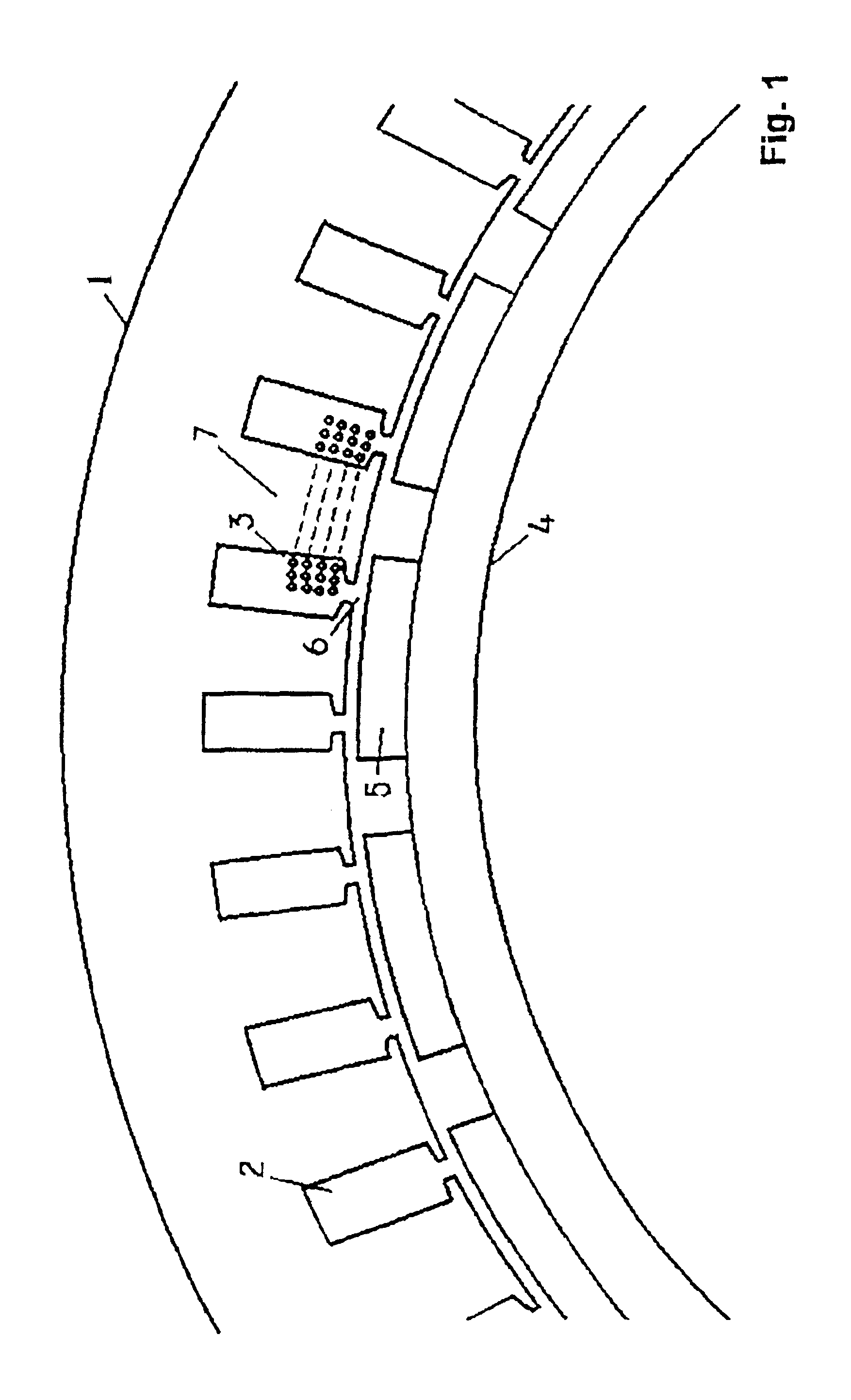
FIG. 1 shows a sectional view of a part of a generator according to the prior art. The figure shows a stator (1) which has recesses (2) with coils (3) wound in the traditionally manner, i.e. from a given recess to another, depending on the phases of the current generated. Also shown is a rotor (4) with magnets (5) spaced apart from the boundary of the rotor (4). Between the magnets (5) on the rotor (4) and the stator (1) there is an air gap.

When the rotor (4) moves via a shaft (not shown) with respect to the stator (1), the magnets (5) are moved past the coils (3) and current is thus induced in these.

If current is supplied to the coils (3), a magnetic field will make the rotor (4) and the shaft move, and the electrical machine functions as a motor.

The construction according to the prior art has the disadvantages already mentioned in the Background of the Invention.

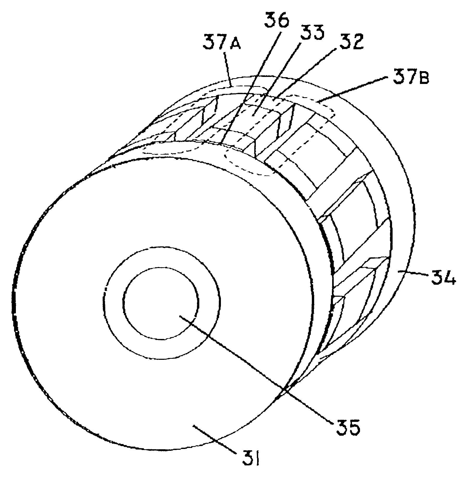
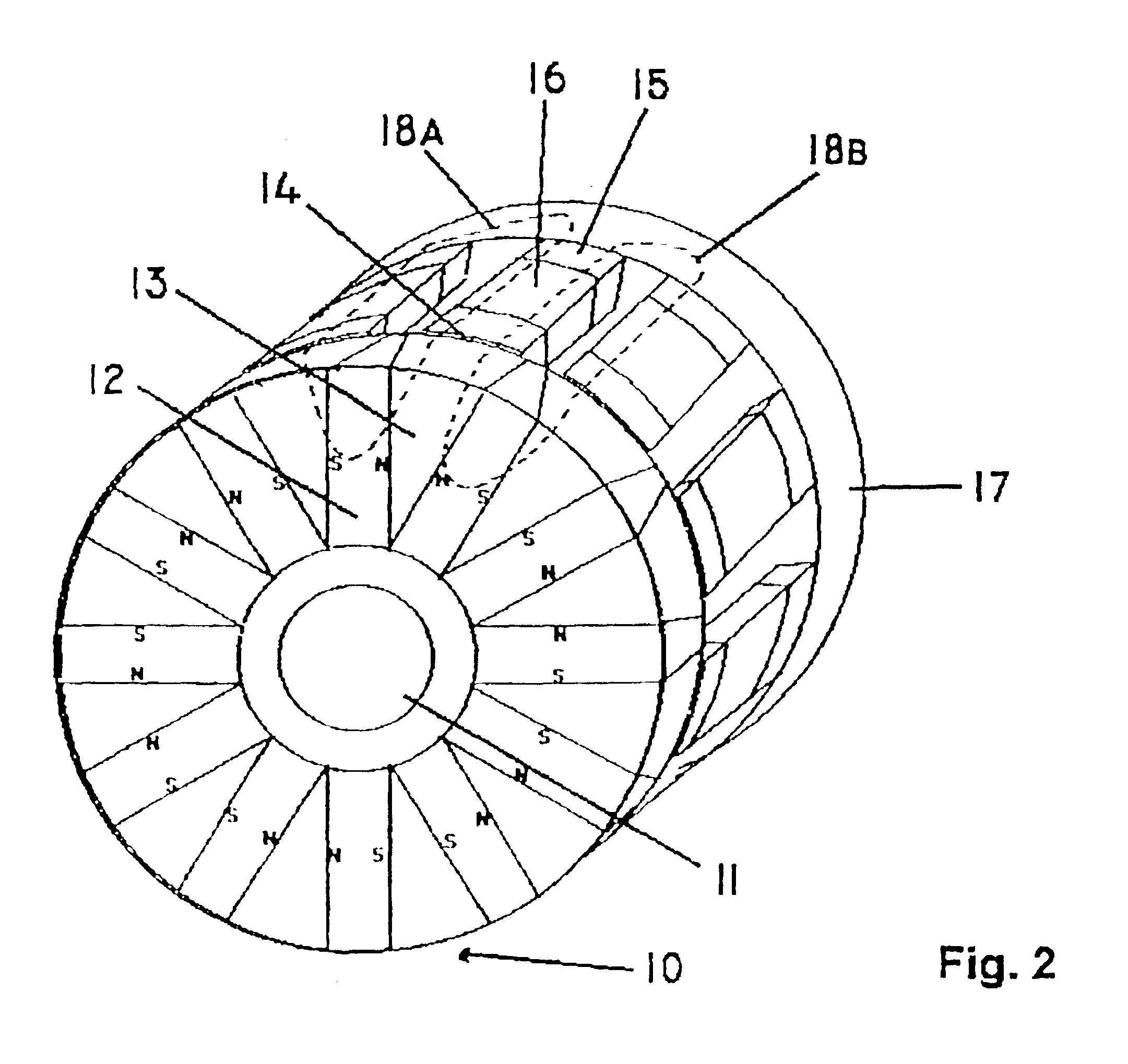
FIG. 2 shows a schematic view of an embodiment according to the invention. The Figure shows a pole wheel (10) which func...


PUM


Abstract

This invention relates to an electric multiple motor/generator with axial magnetic flux. Thus a generator/motor or electrical machine in which a magnetic flux path through one or more pole legs or pole cores surrounded by current windings or coils is provided. This allows a high density of the magnetic flux to be passed through the pole legs or cores, which results in a low consumption of material for the pole legs or pole cores compared with prior art machines, where for example a large stator diameter may be needed in order to conduct a high magnetic flux. Additionally the generator/motor or electrical machine is very efficient both at a low and a high number of revolutions. According to another aspect of the invention a multiple phase output without enlarging the diameter of the generator is provided.

Description

FIELD OF INVENTIONThis present invention relates to an electrical machine, and more particularly to a synchronous machine. The electrical machine can operate either as a motor or generator, as will be described later and will just be called generator in the following.BACKGROUND OF THE INVENTIONElectrical generators may be used in many different fields. When a generator is e.g. used in a wind turbine, one of the more important economic parameters, with respect to the dimensioning of the wind turbine, is the size of the housing. It is therefore of great importance to be able to minimize the diameter of the wind turbine. In order to minimize the housing one has to minimize the gearbox / gear wheel connecting the wing and the generator. This can be achieved by providing a generator that has a relatively large effect per revolution.One way to achieve this is to have a generator with as small a radial extent as possible, since the generator occupies a relative large amount of space in the h...

Claims


Application Information

Patent Timeline
IPC IPC(8): H02K1/27H02K1/14H02K21/12H02K21/24H02K21/14
CPCH02K1/14H02K1/141H02K1/27H02K21/12H02K21/24H02K1/2793Y02E10/725Y02E10/72H02K1/2795
Inventor LARSEN, KIM DAMRASMUSSEN, PETERLARSEN, UFFE DAM
Owner MULTIPOLGENERATOR APS
Why Eureka
Try Eureka