Capacitive probe for measuring the level of an electricity-conducting liquid in a vessel and method of manufacturing such a probe

a technology of capacitive probes and liquids, which is applied in the direction of liquid/fluent solid measurement, machines/engines, instruments, etc., can solve the problems of loss of precision, deterioration of the level of the capacitive probe, and difficulty in forming a uniform and thin insulating layer on the metallic rod or wall, etc., to achieve good precision and stable in time

Inactive Publication Date: 2005-01-18
INST FR DU PETROLE
View PDF18 Cites 15 Cited by
  • Summary
  • Abstract
  • Description
  • Claims
  • Application Information

AI Technical Summary

Benefits of technology

The capacitive probe according to the invention allows continuous measurement of the level of a conducting fluid in a vessel with g...

Problems solved by technology

This type of measurement works well even at relatively high pressures and temperatures as long as the interface between phases is clear, but it loses precision when the liquid is highly emulsified.
First of all, it is difficult to deposit a uniform and thin insulating layer on a metallic rod or wall.
The probes generally wor...

Method used


Image

  • Capacitive probe for measuring the level of an electricity-conducting liquid in a vessel and method of manufacturing such a probe
  • Capacitive probe for measuring the level of an electricity-conducting liquid in a vessel and method of manufacturing such a probe

Examples


Embodiment Construction

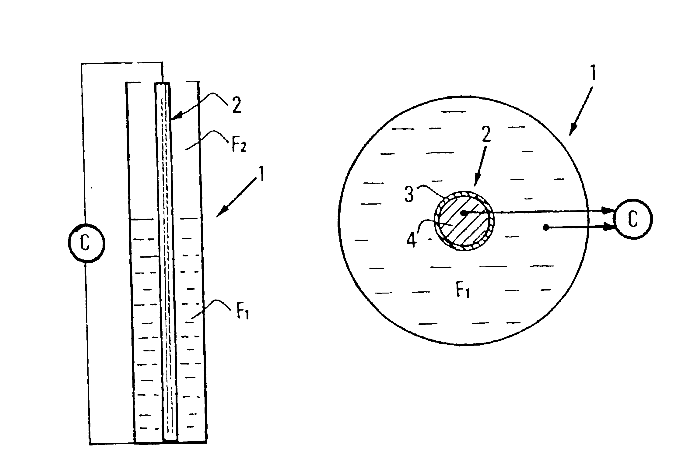
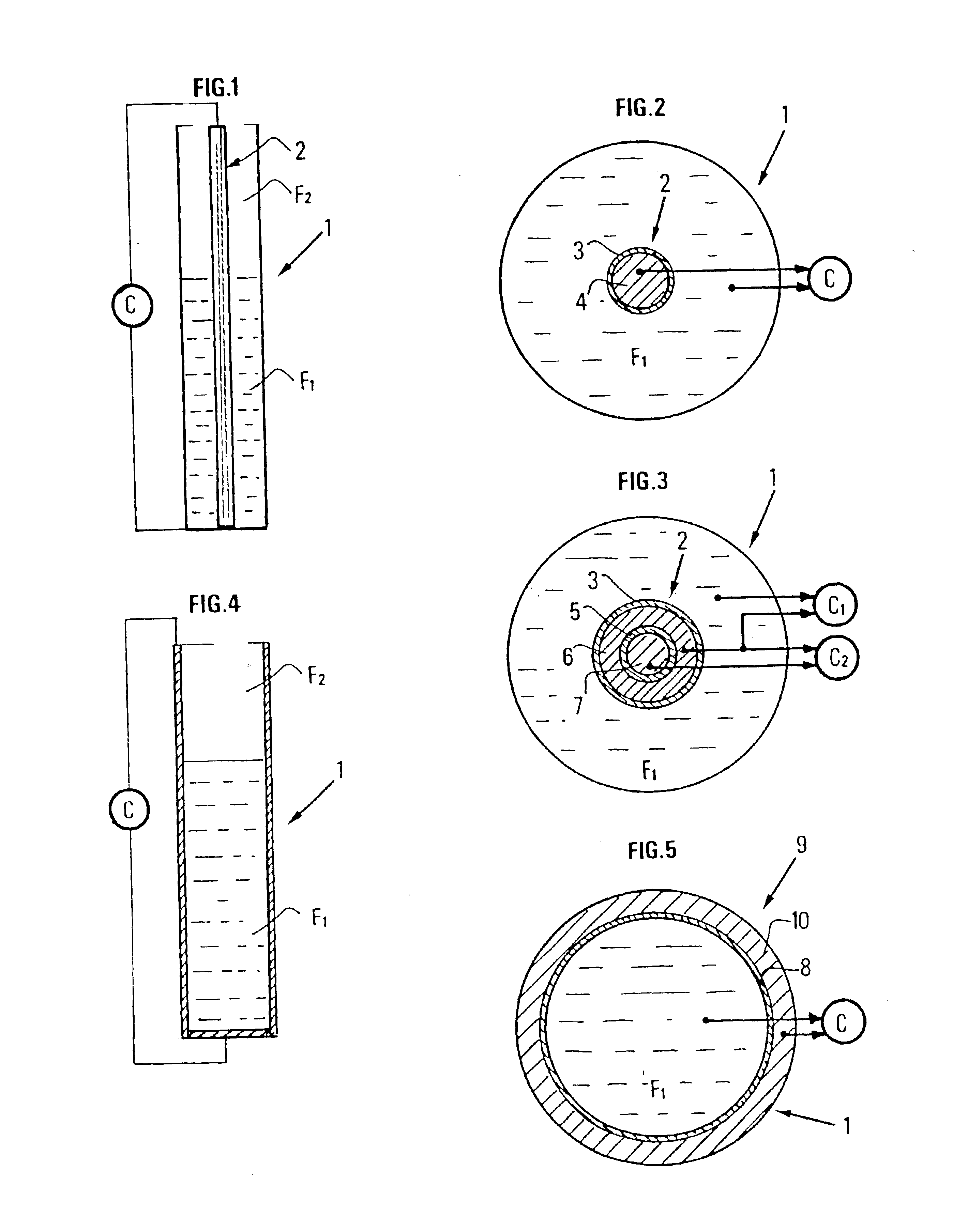
The capacitive probe according to the invention is suited to continuously measure the level of the interface between an electrically conductive fluid Fl (brine for example) and another, non-conducting fluid F2 (a gas or a liquid such as oil), contained in an elongate vessel 1 (FIG. 1), by determining the capacitance of the capacitor consisting of conducting fluid Fl (first electrode) and a central rod 2.

This rod 2 comprises (FIG. 2) a tube 3 made of a heat-resisting dielectric material. This tube, obtained by moulding or extrusion, is baked at a high temperature (1000° to 2000° C. for example). Second electrode 4 is formed within insulating tube 3. It is preferably made by filling the inside of tube 3 with a fusible metal alloy so selected that its melting temperature is naturally well above the maximum operating temperature specified for the capacitive probe, while remaining greatly below the baking temperature of the heat-resisting material. An alloy based on metals such as zinc, ...


PUM


Abstract

Capacitive probe measuring the level, in a vessel and with high precision, of the interface between a conducting fluid (F1) and a non-conducting fluid (a gas or oil for example), suited to work under high pressure and high temperature conditions. The probe comprises a preferably tubular insulating layer (3) made of a dielectric heat-resisting material (a metal oxide such as zirconia or alumina) baked at a high temperature, with a first face in contact with conducting fluid (Fl) and an opposite face in contact with a second electrode (4), consisting for example of a coating or of a layer made of a fusible alloy deposited on the opposite face of insulant (3), selected according to the temperature range within which the capacitive probe is intended to work, or possibly of an added tube. Alloys based on zinc, tin, copper, etc, can for example be used. A second capacitor of the same type used for temperature compensation of the first one can be placed within the tubular insulating layer. Its capacitance is for example of the order of 1 nF. The probe can be applied in laboratory apparatuses working under high pressure and high temperature conditions, notably in petrophysical test cells.

Description

BACKGROUND OF THE INVENTION1. Field of the InventionThe present invention relates to a capacitive probe for measuring the level of an electrically conductive liquid in a vessel, particularly suited for high pressure and high temperature applications, and a method of manufacturing such a probe.2. Description of the Prior ArtExamples of well-known methods intended to measure the evolution of the level of a liquid in a vessel are optical methods according to which the progress of a float is monitored by automatic control through a transparent window provided vertically in the wall. This type of measurement is suited only for clean liquids which do not affect the transparency of the window.There are also ultrasonic methods where the level of the liquid in a vessel is measured by measuring the time of propagation of pulses reflecting on the surface. This type of measurement works well even at relatively high pressures and temperatures as long as the interface between phases is clear, but...

Claims


Application Information

Patent Timeline
IPC IPC(8): G01F23/26G01F23/22
CPCG01F23/268
Inventor LENORMAND, ROLANDCHAPUT, CHRISTOPHE
Owner INST FR DU PETROLE
Why Eureka
Try Eureka