High voltage load resistor array

a load resistor and high voltage technology, applied in the direction of resistor details, liquid resistors, resistor mounting/supporting, etc., can solve the problems of few commercially available options, unadjustable, and expensive construction, and achieve the effect of high voltage, easy modification, and inexpensive production

Inactive Publication Date: 2005-01-18
JEFFERSON SCI ASSOCS LLC
View PDF0 Cites 12 Cited by
  • Summary
  • Abstract
  • Description
  • Claims
  • Application Information

AI Technical Summary

Benefits of technology

It is therefore an object of the present invention to provide a high voltage resistor system that is relatively inexpensive to produce and which can be readily modified to alter its voltage / amperage handling capabilities.
It is another object of the present invention to provide a high voltage resistor system that, in the case of voltage flash-over or arcing or other damaging failure can be readily repaired at low cost.

Problems solved by technology

Currently there are only a few commercially available options for resistors capable of handling such loads.
While solid carbon resistors are capable of handling such loads, they are very expensive to construct, require long lead times to obtain, are not adjustable to ohmic values other than those for which they were designed and built, i. e. not flexible, and if high voltage flash-over or arcing occurs significant damage will be inflicted and the costly resistor will have to be replaced because repair is not normally an option.
Metal alloy banks demonstrate similar shortcomings in that they are even more expensive to construct, require long lead times to obtain, are not adjustable to ohmic values other than those for which they were designed and built and furthermore, are usually designed to handle larger current loads at much lower operating voltages than those encountered in, for example, the operation of free electron lasers as just described.
Thus, while such prior art devices may meet the needs of certain applications, their high cost, relative inflexibility in terms of modification for load variation, and their relative inability to be readily repaired make them inappropriate for use in high voltage applications that may require voltage or amperage handling variation and could result in damage to the resistor.

Method used


Image

  • High voltage load resistor array
  • High voltage load resistor array
  • High voltage load resistor array

Examples


Embodiment Construction

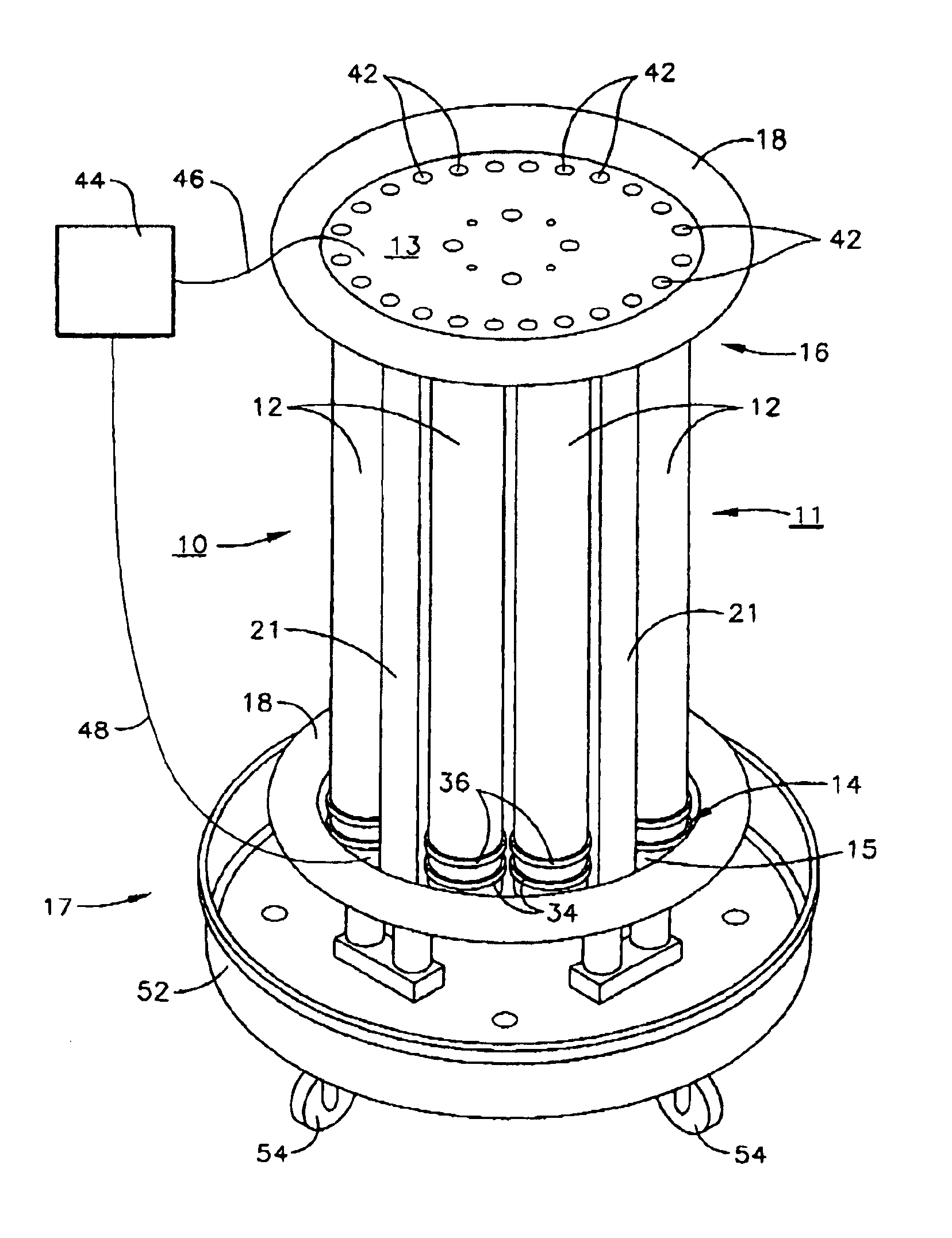
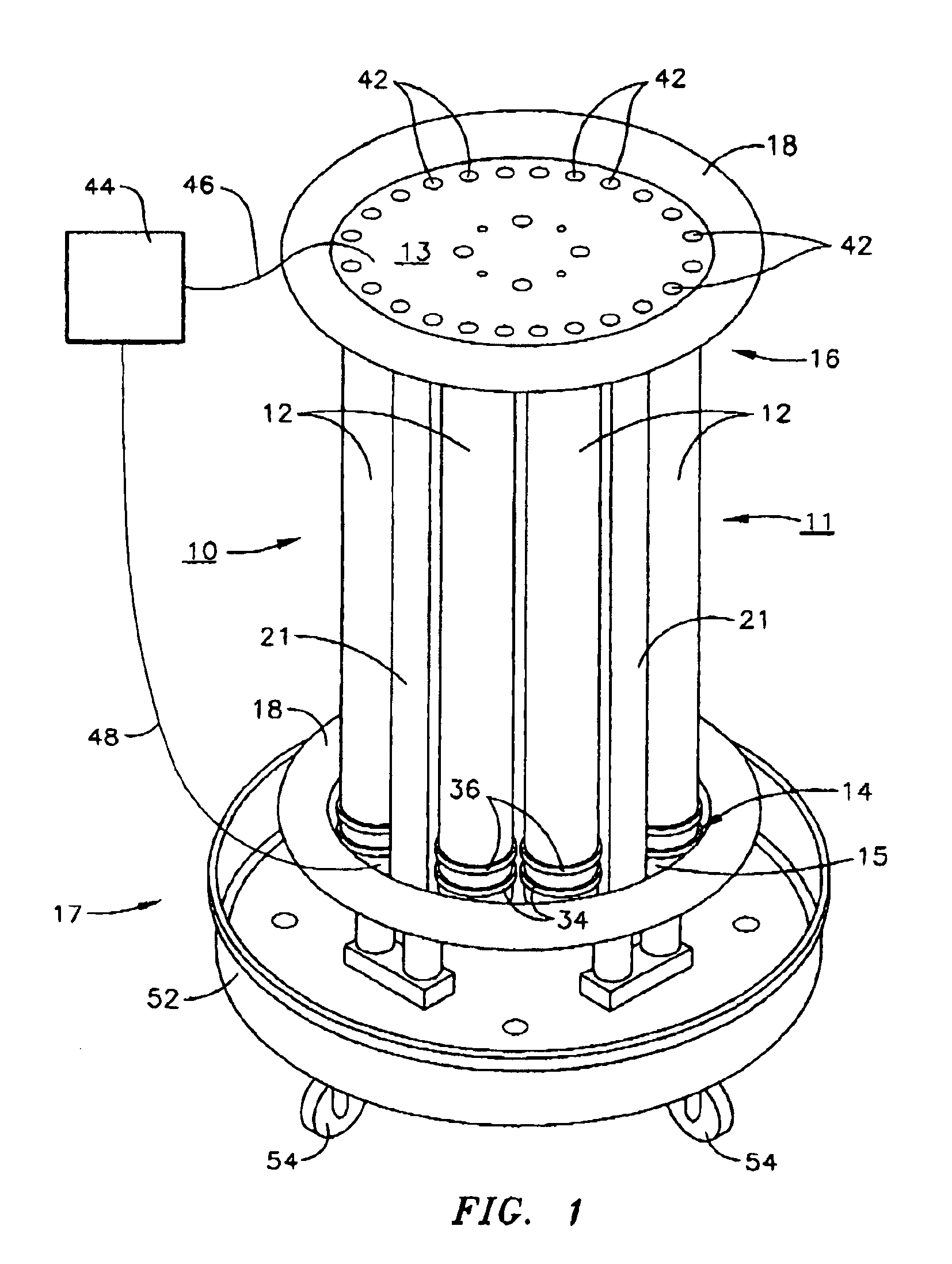
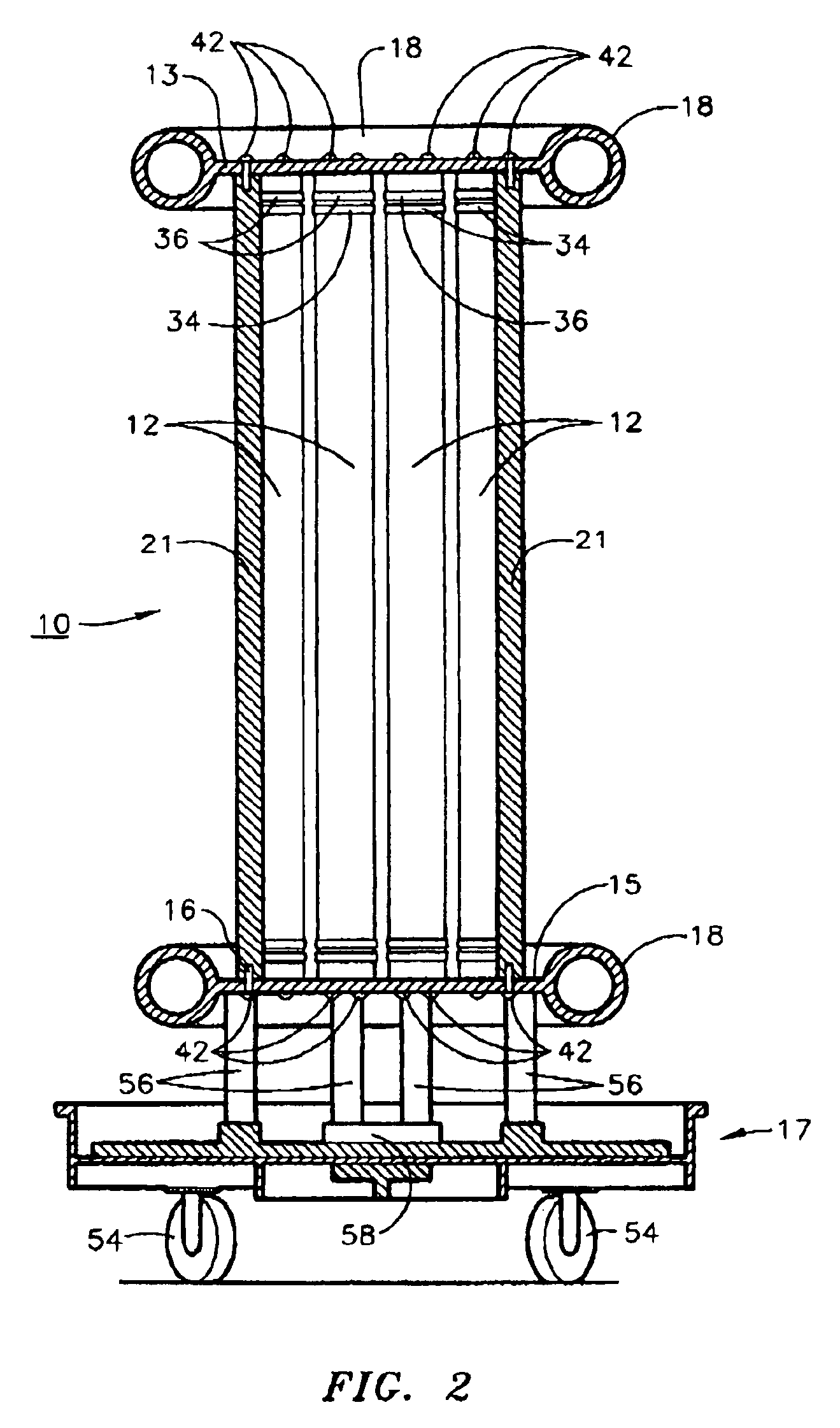
Referring now to the accompanying figures, the resistor array 10 of the present invention comprises an array of resistor elements 12 which array has first and second ends 14 and 16. Located about ends 14 and 16 are corona rings 18 that serve to protect resistor array 10 from damage by reducing the possibility of arcing or voltage flash-over. Each of resistor elements 12 is contactingly attached to end plates 13 and 15 as described below. Bottom end plate 15 is in turn preferably attached to a carriage 17 for ease of movement of resistor array 10 from location to location.

Corona rings 18 serve to minimize the possibility that any sharp edges on end plates 13 and 15 (described below) would emit corona in the case of a high voltage application resulting in arcing or voltage flash over and preferably form an integral part of end plates 13 and 15 (described below). Corona rings 18 must be of a size adequate to provide a required safety margin in the case of any potential arcing or voltag...


PUM


Abstract

A high voltage resistor comprising an array of a plurality of parallel electrically connected resistor elements each containing a resistive solution, attached at each end thereof to an end plate, and about the circumference of each of the end plates, a corona reduction ring. Each of the resistor elements comprises an insulating tube having an electrode inserted into each end thereof and held in position by one or more hose clamps about the outer periphery of the insulating tube. According to a preferred embodiment, the electrode is fabricated from stainless steel and has a mushroom shape at one end, that inserted into the tube, and a flat end for engagement with the end plates that provides connection of the resistor array and with a load.

Description

FIELD OF THE INVENTIONThe present invention relates to high voltage resistors and more particularly to such a high voltage resistor that is capable of handling upwards of 600,000 volts DC at a current of 2 amps or more without arcing or surface breakdown.BACKGROUND OF THE INVENTIONIn certain leading edge technological applications such as the operation of free electron lasers and the like, there exists the need to be able to safely handle very high voltages, on the order of above 500,000 volts, in, for example, power supplies and the like. In such applications, load resistors capable of handling such voltages are a necessary requirement. In such applications, the presence of electrical current on the order of 2 amps or higher is also quite possible.Currently there are only a few commercially available options for resistors capable of handling such loads. Among these are solid carbon resistors and high resistance metal alloy load banks. While solid carbon resistors are capable of han...

Claims


Application Information

Patent Timeline
Patent Type & Authority Patents(United States)
IPC IPC(8): H01C13/02H01C13/00H01C1/01H01C1/014
CPCH01C13/02H01C1/014
Inventor LEHMANN, MONTY RAY
Owner JEFFERSON SCI ASSOCS LLC
Why Eureka
Try Eureka