
Computer containing clock source using a PLL synthesizer

Inactive Publication Date: 2005-01-18
ALPS ALPINE CO LTD
View PDF4 Cites 21 Cited by
  • Summary
  • Abstract
  • Description
  • Claims
  • Application Information

AI Technical Summary

Benefits of technology

Accordingly, an object of the present invention is to arrest the occurrence of unnecessary multiplication-induced signals that cause malfunctions and interference with other electronic devices, and to reduce the current consumption and heating of the CPU 114.
Another object of the present invention is to enable the use of a clock signal containing very few unnecessary signals such as harmonics and to enable the frequency of the clock signal to be easily reduced at a power save mode.

Problems solved by technology

Such unnecessary signals B invade various circuits through the bus within the computer and cause the circuits to malfunction.
Also, the unnecessary signals B leak out of the computer and invade circuits of other devices, causing the circuits to malfunction.
Also, in the above conventional configuration in which a signal multiplied by the multipliers is used as a clock signal, aside from a signal of a desired frequency, many unnecessary signals occur over a wide frequency range.
Such unnecessary signals invade various circuits through a bus or the like within equipment such as a personal computer and cause the circuits to malfunction.
Also, such unnecessary signals are radiated out of the personal computer, causing interference with other electronic devices.
Since the frequency multiplier uses nonlinear characteristics to generate harmonics and takes out of them only harmonics having necessary frequencies, a configuration for switching frequencies is complicated.

Method used


Image

  • Computer containing clock source using a PLL synthesizer
  • Computer containing clock source using a PLL synthesizer
  • Computer containing clock source using a PLL synthesizer

Examples


Embodiment Construction

Hereinafter, a first embodiment of a computer of the present invention is described with reference to FIGS. 1 and 2.

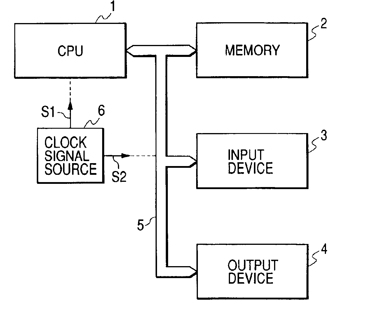
FIG. 1 is a block diagram showing a configuration of a computer in a first embodiment of the present invention. The computer is made up of CPU 1, and peripheral devices 2, 3, and 4 such as memory, input device, and output device. Data is transmitted between the CPU 1, and the peripheral devices 2, 3, and 4 through a bus 5. The computer requires a clock signal (referred to as a CPU clock signal) for running the CPU and a clock signal (referred to as a bus clock signal) for transmitting data through the bus 5, and a clock signal source 6 for the signals is provided within the computer. Two signals S1 and S2 are outputted from the clock signal source 6, with the signal S1 used as a CPU clock signal and the signal S2 as a bus clock signal.

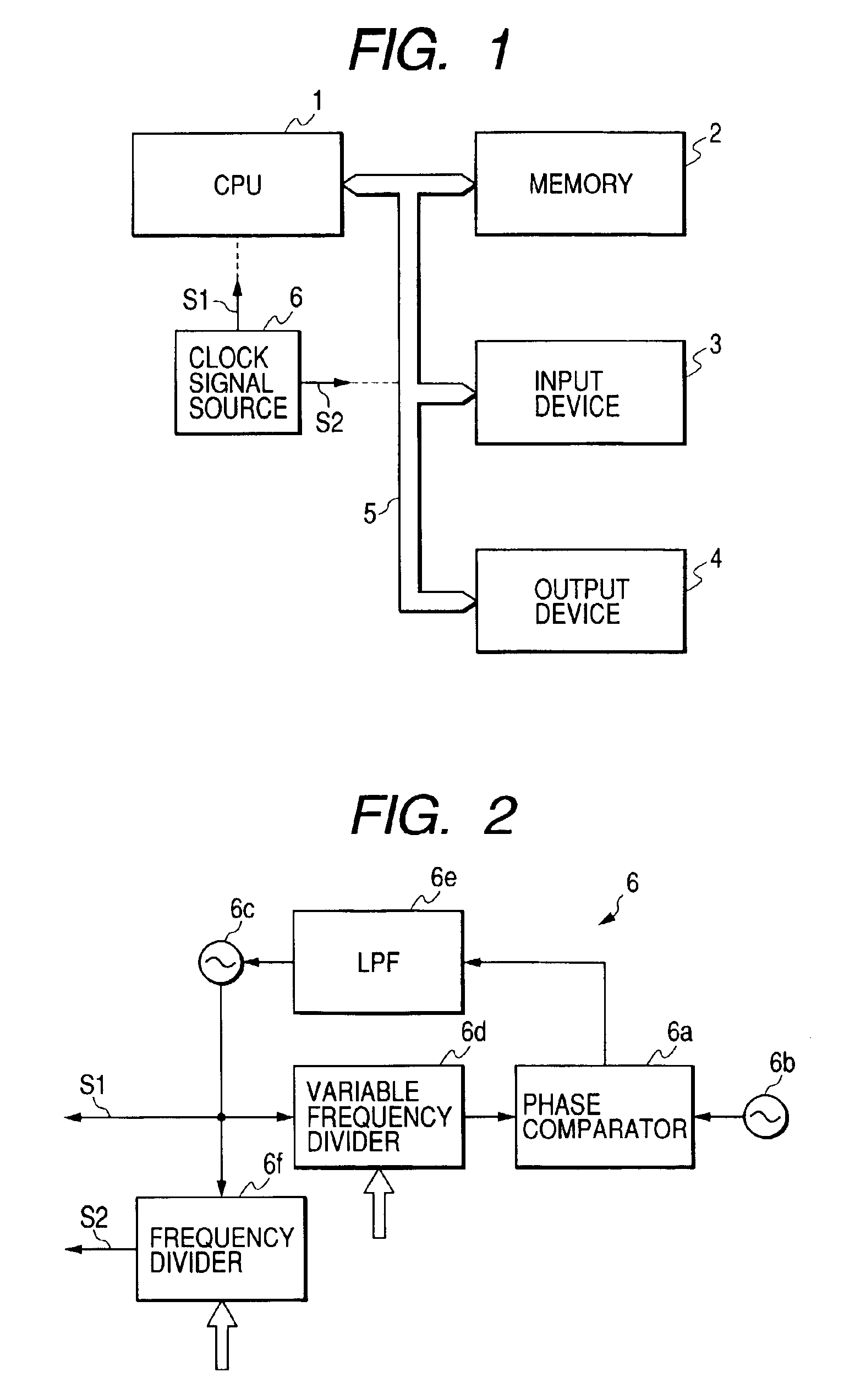
The clock signal source 6 is constituted by a PLL synthesizer as shown in FIG. 2. In FIG. 2, one input end of a phase comparator 6a is s...


PUM


Abstract

A computer of the present invention contains: a CPU; plural peripheral devices controlled by the CPU; a data transmission bus between the CPU and the peripheral devices and between the peripheral devices; and a clock signal source for supplying clock signals for CPU operation and data transmission. The clock signal source contains a PLL synthesizer, and two clock signals (one for the CPU and the other for the bus) are outputted from the PLL synthesizer to stop unnecessary signals (other than the clock signals) from being produced.

Description

BACKGROUND OF THE INVENTION1. Field of the InventionThe present invention relates to a computer, and more particularly to the configuration of a clock signal source for running the computer. It also relates to a computer having a power saving function.2. Description of the Prior ArtA conventional clock signal source used in personal computers and the like, as shown in FIG. 8, comprises a combination of a reference oscillator 110 and frequency multipliers 111 and 113 provided within a computer. In FIG. 8, the reference oscillator 110 oscillates at several megahertz and the frequency of an oscillation signal is multiplied tens of times to an appropriate frequency by the first frequency multiplier 111. The multiplied signal is used as a clock signal for a bus 112 within the computer.The signal multiplied by the first frequency multiplier 111 is multiplied to a higher frequency by the second frequency multiplier 113. The second frequency multiplier 113 is provided within the CPU 114 of ...

Claims


Application Information

Patent Timeline
IPC IPC(8): G06F1/32G06F1/08G06F1/06
CPCG06F1/06G06F1/08G06F1/324G06F1/3203Y02B60/1217Y02D10/00
Inventor YATSUDA, SENICHIROIKARASHI, YASUHIROHIROSE, YOSHITAKA
Owner ALPS ALPINE CO LTD
Features
  • Generate Ideas
  • Intellectual Property
  • Life Sciences
  • Materials
  • Tech Scout
  • Unparalleled Data Quality
  • Higher Quality Content
  • 60% Fewer Hallucinations
Learn More