
CML (current mode logic) OCD (off chip driver)-ODT (on die termination) circuit for bidirectional data transmission

a logic and data transmission technology, applied in logic circuit coupling/interface arrangement, logic circuit details, pulse technique, etc., can solve the problems of increasing increasing the cost of integrated circuits, and increasing the so as to reduce the physical size requirement, reduce the overall number of resistors used, and facilitate the route and placement of the invention on the integrated circuit

Inactive Publication Date: 2005-01-25
POLARIS INNOVATIONS LTD
View PDF8 Cites 26 Cited by
  • Summary
  • Abstract
  • Description
  • Claims
  • Application Information

AI Technical Summary

Benefits of technology

"The present invention provides an apparatus that can be used both as an off chip driver and as an on die termination. This reduces the physical size requirements and simplifies the production of the integrated circuit. The overall number of resistors used is reduced, making the production of the integrated circuit easier. The technical effects of the invention are reduced physical size requirements, simplified production process, and reduced number of resistors needed."

Problems solved by technology

One disadvantage of the prior art is that through the use of separate OCD and ODT circuits, more resistors are used.
In integrated circuits, it can be relatively difficult to produce resistors of a specific desired value, especially if the resistance of the resistors is large.
This may lead to a more expensive integrated circuit.
A second disadvantage of the prior art is that integrated resistors (especially resistors with large resistances) may be physically large in size.
Therefore, the use of a relatively large number of resistors may result in an integrated circuit that is physically large.
Additionally, the presence of the large resistors may make it more difficult to route and place circuitry in the integrated circuit.

Method used


Image

  • CML (current mode logic) OCD (off chip driver)-ODT (on die termination) circuit for bidirectional data transmission
  • CML (current mode logic) OCD (off chip driver)-ODT (on die termination) circuit for bidirectional data transmission
  • CML (current mode logic) OCD (off chip driver)-ODT (on die termination) circuit for bidirectional data transmission

Examples


Embodiment Construction

The making and using of the presently preferred embodiments are discussed in detail below. It should be appreciated, however, that the present invention provides many applicable inventive concepts that can be embodied in a wide variety of specific contexts. The specific embodiments discussed are merely illustrative of specific ways to make and use the invention, and do not limit the scope of the invention.

The present invention will be described with respect to preferred embodiments in a specific context, namely an integrated circuit using a current mode logic circuit to perform both as an off chip driver and as an on die termination circuit. The invention may also be applied, however, to other integrated circuits using other forms of logic where the desire is to have high-speed communications with emphasis placed upon minimizing size and costs by using multifunction circuitry.

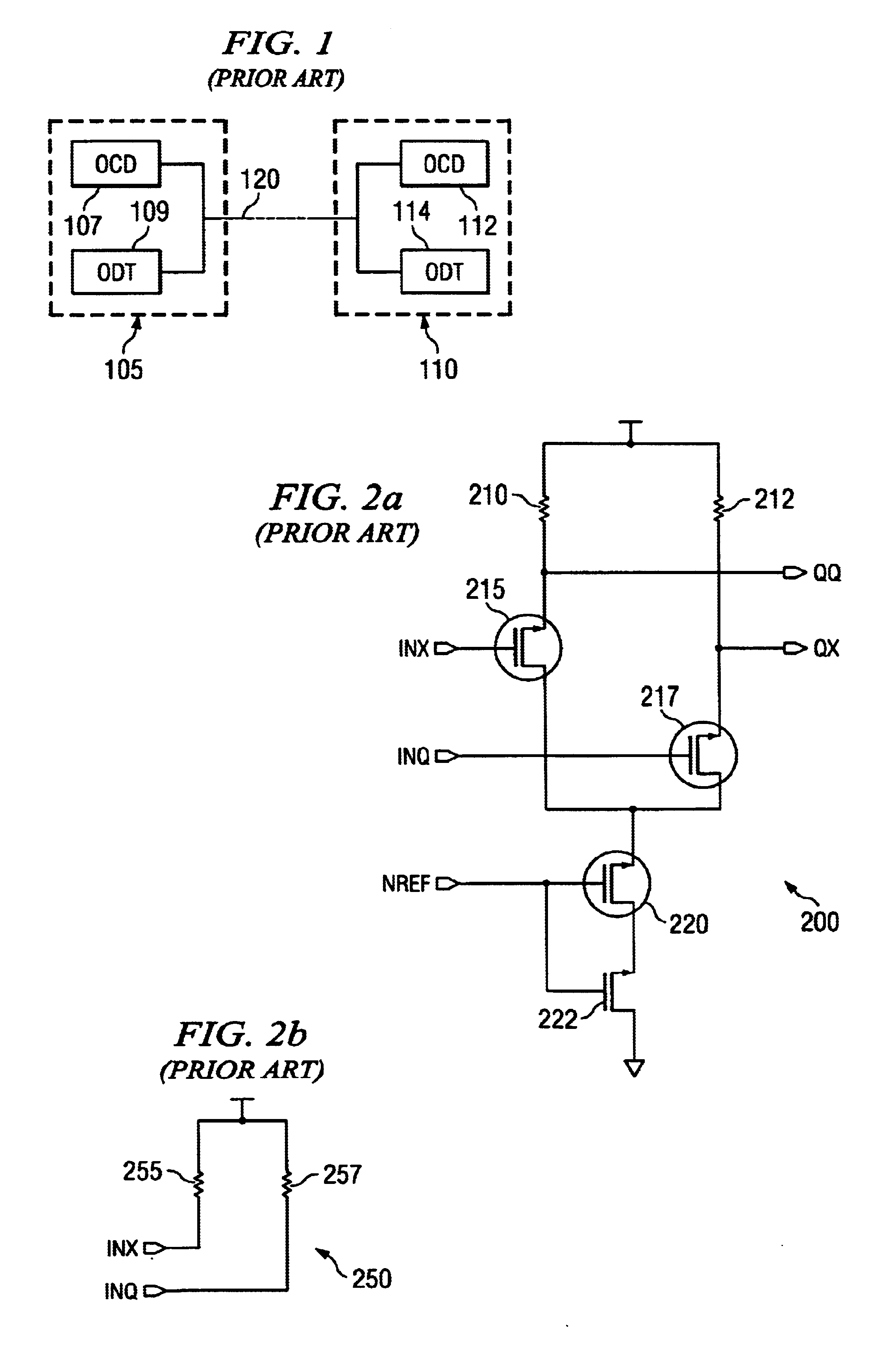
With reference now to FIG. 1, there is shown a diagram illustrating a pair of integrated circuits 105 and 11...


PUM


Abstract

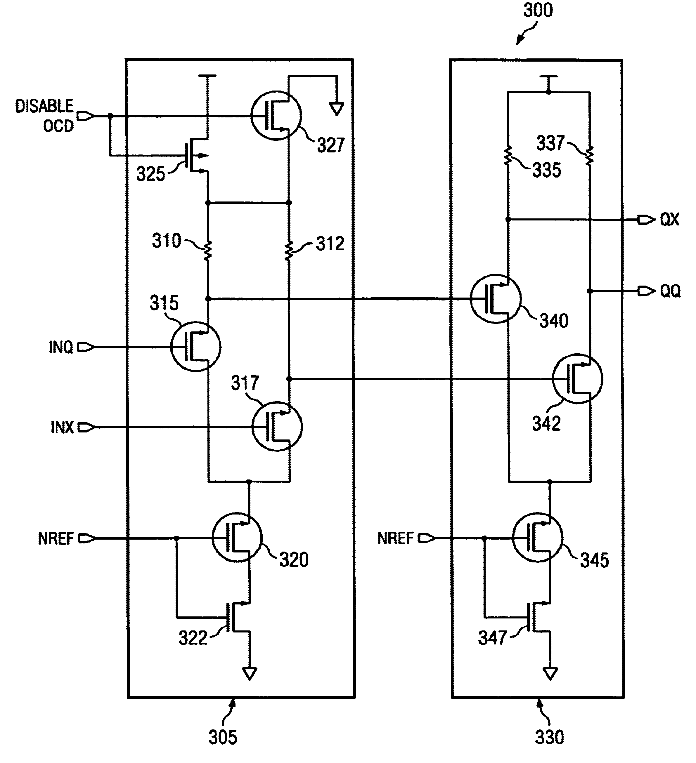
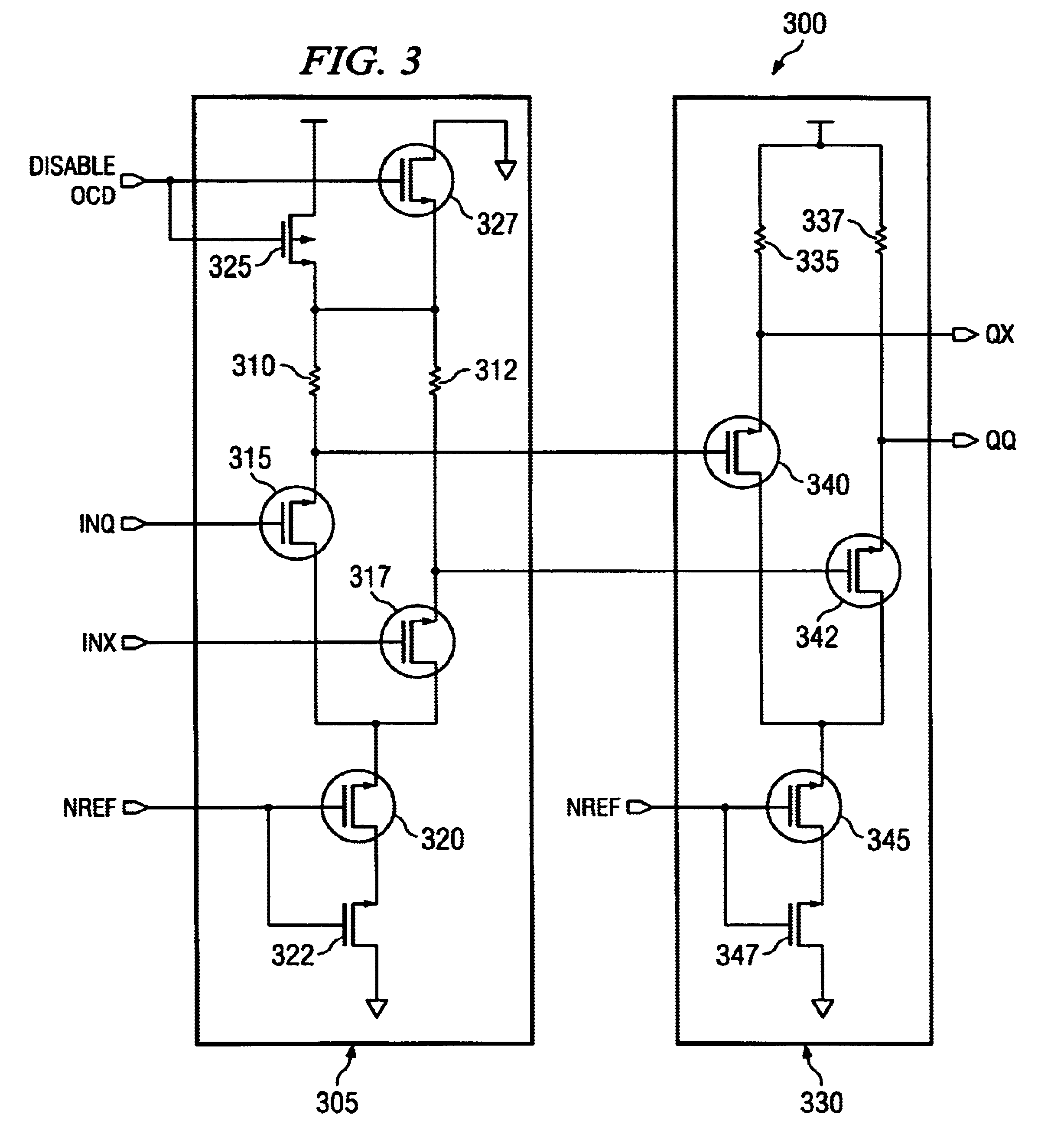
An apparatus for use as both an off chip driver (OCD) and an on die termination (ODT) circuits. A preferred embodiment comprises a control circuit (for example, control circuit 305) coupled to a dual function OCD / ODT circuit (for example, OCD / ODT circuit 330) with an enable line coupled to the control circuit. The control circuit may be used to selectively choose OCD and ODT functionality based on a value on the enable line. With the control circuit choosing OCD, the dual function OCD / ODT circuit functions as an OCD circuit, placing signals provided through the control circuit onto a transmission line. With the control circuit choosing ODT, the dual function OCD / ODT circuit becomes terminating resistors for incoming signals on a transmission line. The use of a single circuit for both OCD and ODT functions can save both integrated circuit real-estate and implementation costs due to a reduction in use of circuit elements.

Description

TECHNICAL FIELDThe present invention relates generally to logic circuits, and more particularly to an apparatus that may be used as both an off chip driver and an on die termination for a current mode logic circuit.BACKGROUNDWhen high-speed and low voltage swing data transfer is needed, differential signaling (also commonly referred to as double ended signals), wherein signals are carried on two conductors and the signal is defined as the difference in the two signals. Differential signaling is perhaps the most robust and promising signaling concept. Current mode logic (CML), a design technique commonly used in high speed signaling applications such as communications chips and routers, uses differential signaling.CML is widely used in high-speed applications due to its relatively low power consumption and low supply voltage when compared to other types of logic, such as emitter coupled logic (ECL). CML is also considerably faster than CMOS logic due to its lower voltage swings. CML ...

Claims


Application Information

Patent Timeline
Patent Type & Authority Patents(United States)
IPC IPC(8): H03K19/0185H04L25/02
CPCH03K19/018592H04L25/0282H04L25/0278H04L25/0272H04L25/0294
Inventor VIEHMANN, HANS-HEINRICHLAMMERS, STEFAN
Owner POLARIS INNOVATIONS LTD
Learn More