Holder, system, and process for improving overlay in lithography

a technology of overlay and lithography, applied in the field of vlsi lithography, can solve the problems of limiting alignment accuracy, product failure due to misalignment becoming more prevalent, and difficulty in aligning and overlaying, and achieve the effect of reducing misalignment in the exposure field

Inactive Publication Date: 2005-01-25
BELL SEMICON LLC
View PDF9 Cites 57 Cited by
  • Summary
  • Abstract
  • Description
  • Claims
  • Application Information

AI Technical Summary

Benefits of technology

The present invention provides a holder that can deform a mask or wafer in such a way that much of the image of the mask has a distortion almost ident...

Problems solved by technology

As the demand for products with finer and finer features increases, alignment and overlay is becoming more difficult and product failure due to misalignment is becoming more prevalent.
Even when the alignment metrology is perfect and the measured misalignment of an alignment mark near a chip is very small, distortion in the projected image of the mask due to mask writing errors and lens aberrations and in the wafer due to internal strains from prior processing steps can ultimately limit the alignment accuracy.
There are numerous sources of potential distortion in a mask pattern or in its projected image (if it is a photomask) relative to an existing pattern on a silicon wafer.
The electron beam (e-beam) tool used for mask patterning may make mistakes during the write step.
However, long-range errors, such as an entire segment of a mask being displaced (by 0.25 microns for example) cannot be corrected and, if out of tolerance, the mask must be discarded.
To significantly reduce mask writing errors below current levels would greatly increase mask costs.
Further, the processing of a photomask may introduce strains (mask strain) in its fused-silica substrate and, hence, lead to pattern distortions.
Wavefront errors in the projection lens also may distort the projected image.
Distortion often limits the maximum field size a lens can project.
In scanning systems, some of the lens distortion tends to be averaged out, but at the price of a fuzzy line edge.
However, if different lenses are used f...

Method used


Image

  • Holder, system, and process for improving overlay in lithography
  • Holder, system, and process for improving overlay in lithography
  • Holder, system, and process for improving overlay in lithography

Examples


Embodiment Construction

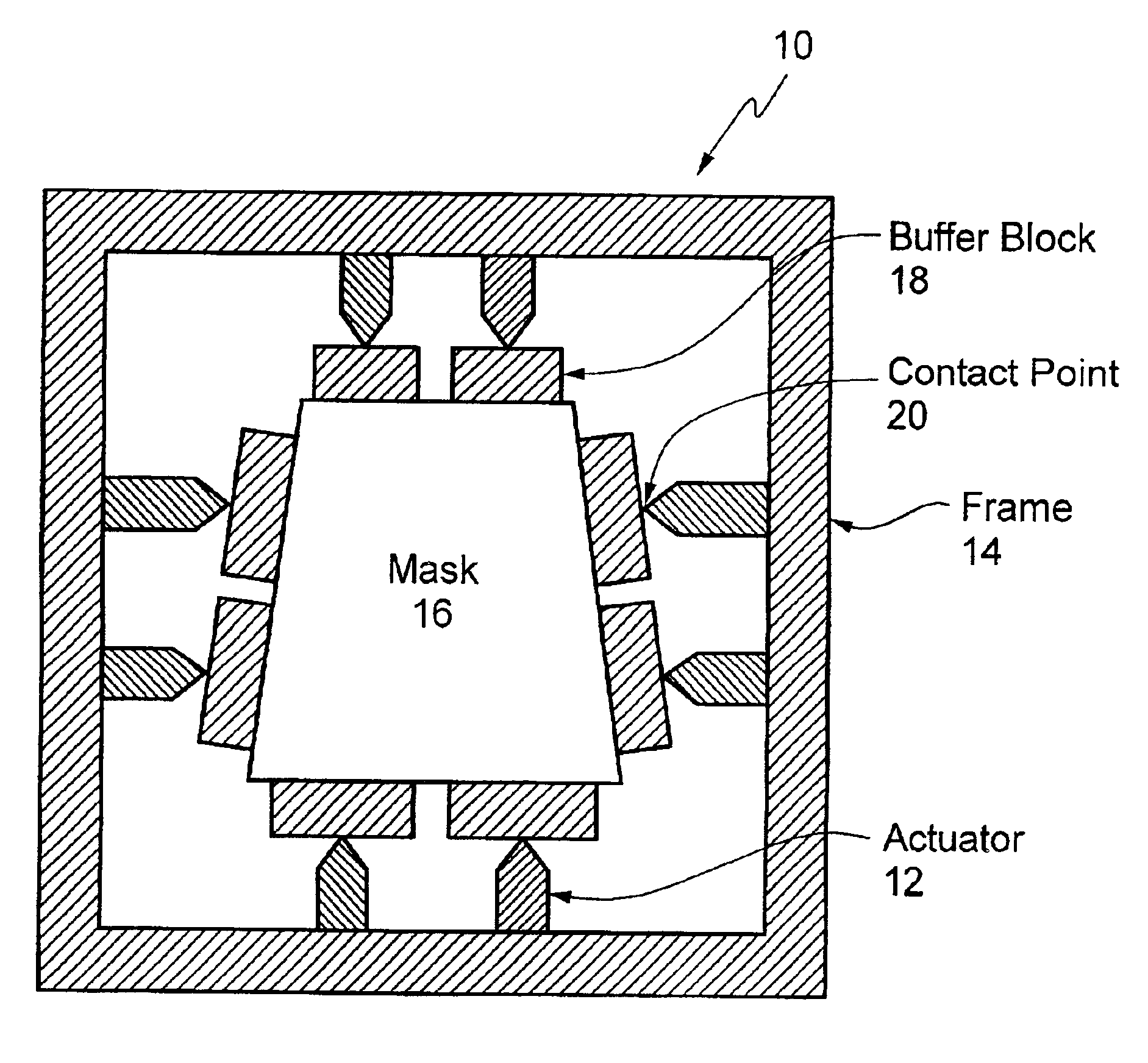
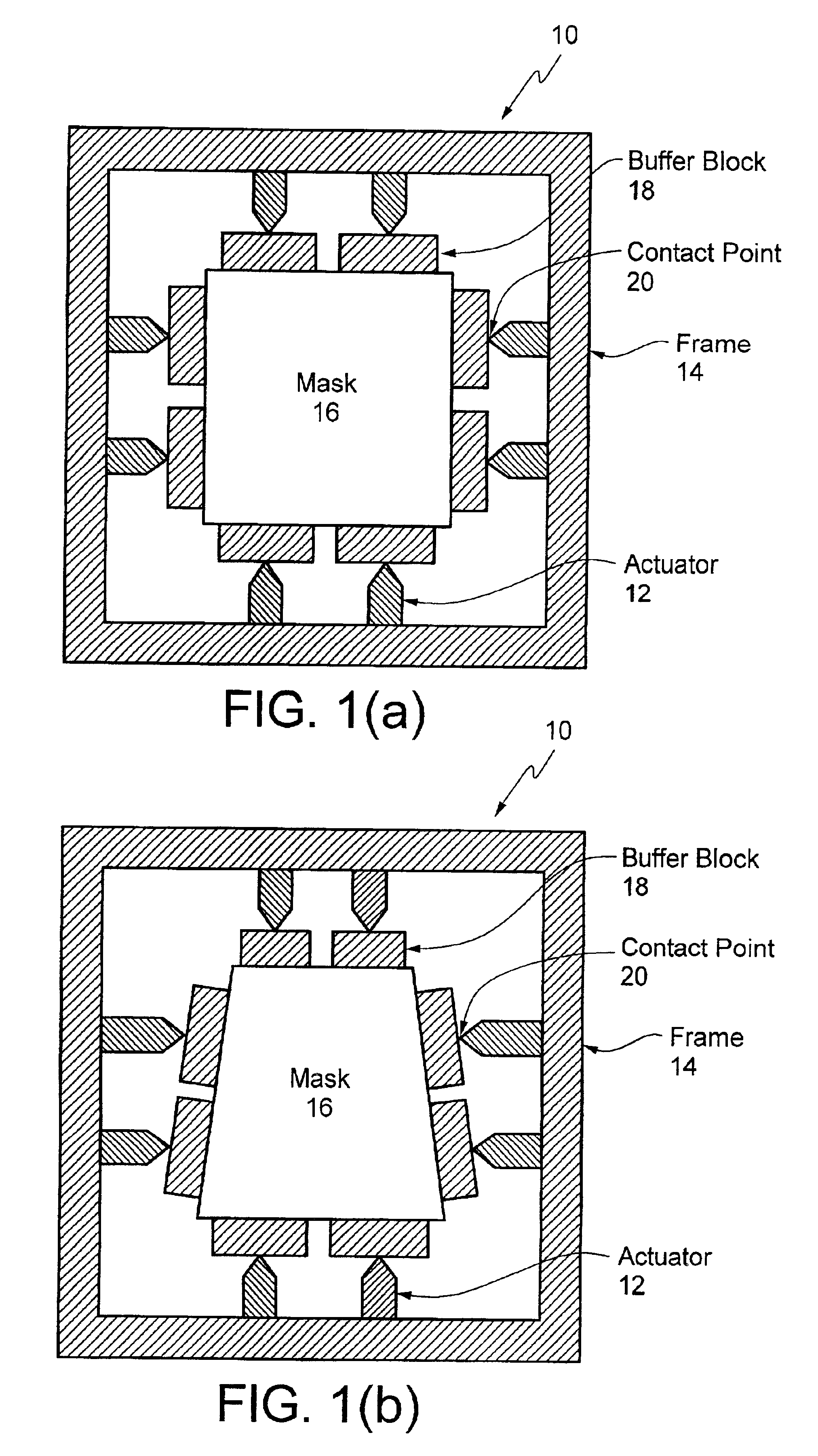
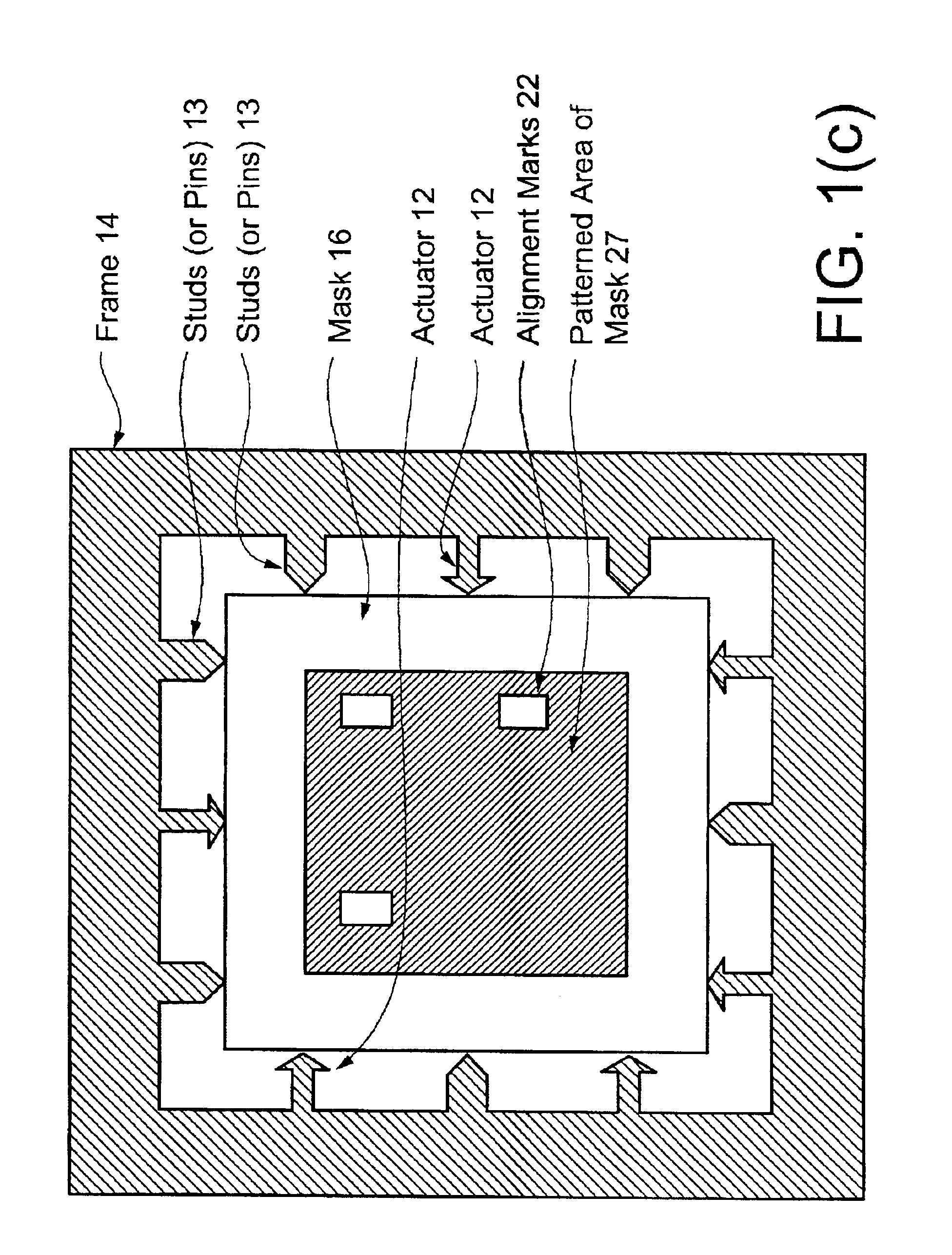
The present invention is generally directed to an adaptive mask holder that uses actuators to apply force to one or more sides of a mask to produce a controlled deformation of the mask that cancels misalignment due to the distortion that is observed between the projected image of the mask and an existing pattern on a wafer.

The present invention is applicable to photolithography. The present invention is also applicable to other lithography types, for example, deep UV and EUV projection lithography and to nano-imprinting techniques. There is no lens in nano-imprinting—the mold, which applies a pattern directly to the wafer, is deformed to match the distortions in the pattern printed on the wafer. The present invention is also useful for overlay and metrology applications.

As described herein, a tool is defined as a machine that uses a mask for some purpose. In VLSI lithography, an image of the mask is recorded on the wafer—thus an EUV scanner step and scan projection camera including ...


PUM


Abstract

A deformable holder, system, and process where long range errors (any of lithography, metrology, or overlay errors) between the image of a mask and an existing pattern on a wafer from a number of potential sources are corrected. The long range errors are determined using either a through-the-lens alignment metrology system or an around-the-lens metrology system. Deformation values are determined to compensate for the longe range errors. The deformation values are determined by either solving simultaneous equations or by finite-element linear-stress-analysis (FEA). The mask or wafer is then distorted, in-plane, by an amount related to the determined deformation values using an actuator such an a piezoelectric ceramic to push or pull the mask or wafer to substantially realign the projected image of the mask and the existing pattern on the wafer.

Description

TECHNICAL FIELDThe present invention relates to the field of VLSI lithography, and more particularly to lithographic overlay.BACKGROUND ARTAs the demand for products with finer and finer features increases, alignment and overlay is becoming more difficult and product failure due to misalignment is becoming more prevalent. Even when the alignment metrology is perfect and the measured misalignment of an alignment mark near a chip is very small, distortion in the projected image of the mask due to mask writing errors and lens aberrations and in the wafer due to internal strains from prior processing steps can ultimately limit the alignment accuracy.There are numerous sources of potential distortion in a mask pattern or in its projected image (if it is a photomask) relative to an existing pattern on a silicon wafer. Some of these sources and their properties are described below.The electron beam (e-beam) tool used for mask patterning may make mistakes during the write step. Fortunately,...

Claims


Application Information

Patent Timeline
IPC IPC(8): G03F7/20
CPCB82Y10/00B82Y40/00G03F7/70633G03F7/70783G03F7/0002Y10S430/168
Inventor WHITE, DONALD L.WOOD, II, OBERT REEVES
Owner BELL SEMICON LLC
Why Eureka
Try Eureka