Video encoding device

a video encoding and video technology, applied in the field of video encoding devices, can solve the problems of increasing data traffic volume over the data transmission lines of the encoding system, separate storage areas of processing units b>12, >16/b>, etc., and achieve the effect of enhancing reducing the resolution of a selected fram

Inactive Publication Date: 2005-01-25
AVAGO TECH INT SALES PTE LTD
View PDF8 Cites 155 Cited by
  • Summary
  • Abstract
  • Description
  • Claims
  • Application Information

AI Technical Summary

Benefits of technology

[0041]The plurality of resolution processors include at least one low resolution processor, for producing low resolution motion analysis, at least one full resolution processor, for producing full resolution motion analysis and at least one hyper resolution processor, for producing hyper resolution motion analysis.
[0042]At least one of the least one low resolution processor reduces the resolution of a selected frame before produc...

Problems solved by technology

For example, one disadvantage of circuit 10 is that each of the processing units 12 and 16 have a separate storage area.
Such Retrieval of large data blocks, many times, greatly increases data traffic volume over the encoding system data transmission lines.
Another disadvantage is that circuit 10 is able to execute all processing and encoding tasks in a serial manner, thereby capable of processing only a single macro-block at a time, requiring high operational processor frequencies.
Another disadvantage of such systems is that all processing and encoding procedures (excluding motion estimation) are executed by the same RISC processor.
In this case, the same circuit performs various types of computations, which makes the utilization of the processor's hardware resources very inefficient.
This method requires a vast number of estimation operations and is thereby extremely resource consuming.
One disadvantage of such machine is that the same operation is performed by all of...

Method used


Image

  • Video encoding device
  • Video encoding device
  • Video encoding device

Examples


Embodiment Construction

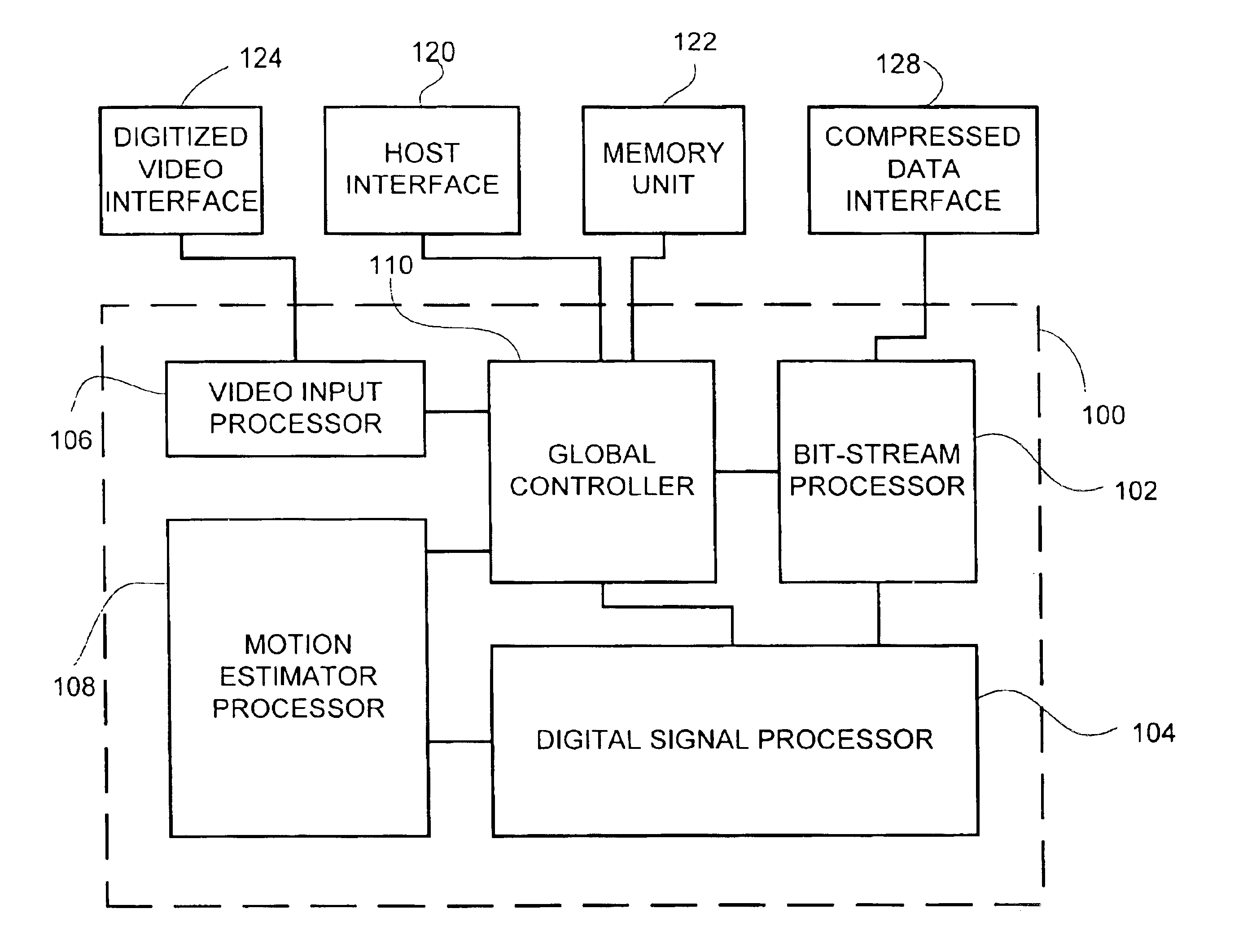
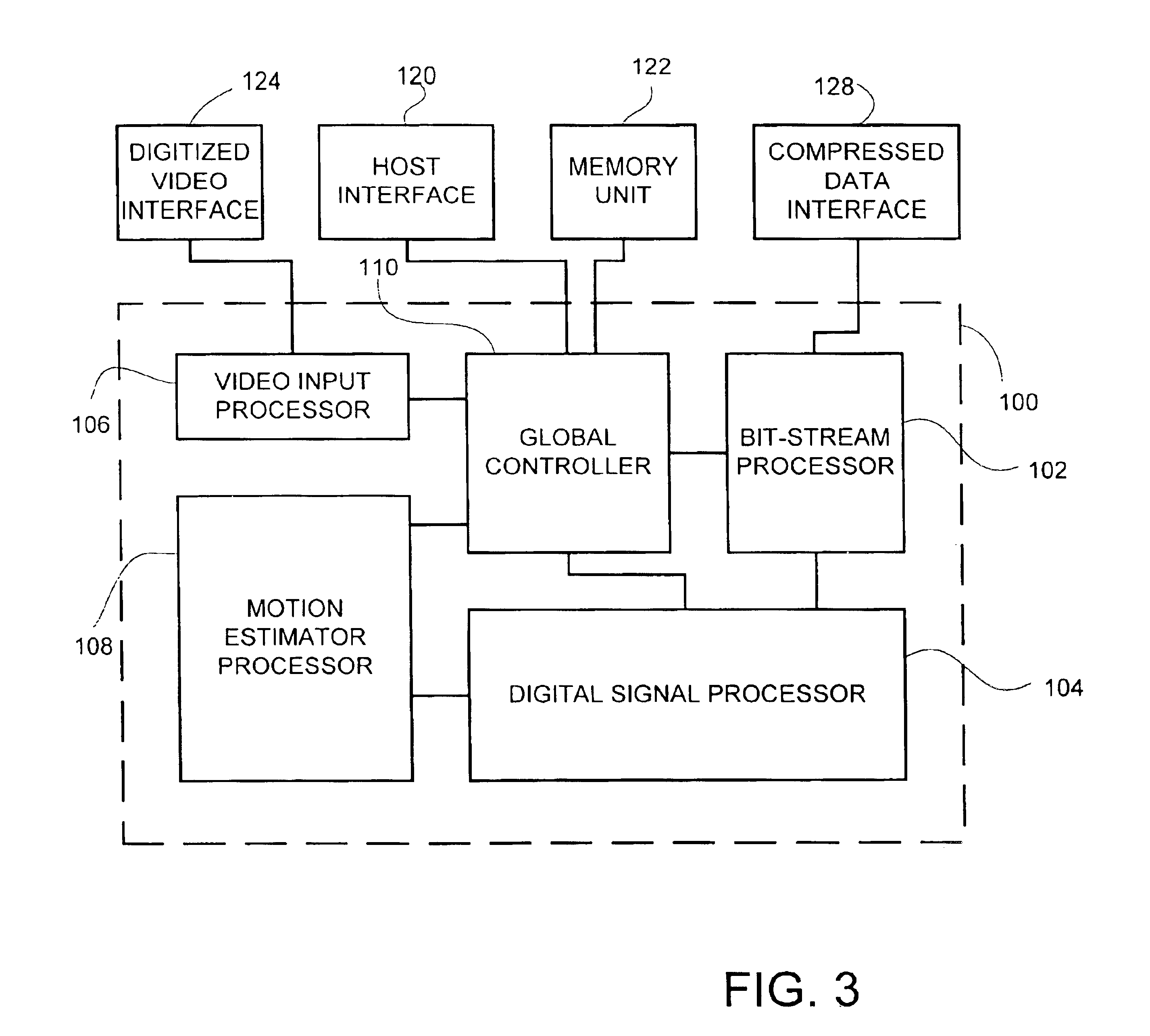
o encoding device of the device of FIG. 3, constructed and operative in accordance with a further preferred embodiment of the invention;

[0054]FIG. 6 is a schematic illustration of a video frame, including three resolution representation of a portion of this frame;

[0055]FIG. 7 is a schematic illustration in detail of the digital signal processor, of the video encoding device of FIG. 3, constructed and operative in accordance with another preferred embodiment of the invention;

[0056]FIG. 8 is a schematic illustration in detail of a digital signal processor, constructed and operative in accordance with a further preferred embodiment of the invention;

[0057]FIG. 9 is a schematic illustration in detail of the video input processor, of the encoding device of FIG. 3, constructed and operative in accordance with a further preferred embodiment of the invention;

[0058]FIG. 10 is a schematic illustration in detail of the bit-stream processor, of the encoding device of FIG. 3, constructed and oper...


PUM


Abstract

Video encoding device including a video input processor, for receiving said video signal, a global controller, for controlling the global operation of the video encoding device, a motion estimation processor, a digital signal processor and a bit-stream processor, wherein the global controller stores encodes commands received from a host interface thereby programming the video input processor, the motion estimation processor, the digital signal processor and the bit-stream processor, the video input processor receives and stores the video signal in an external memory unit, the motion estimation processor retrieves the video signal from the memory unit, generates motion analysis of the video signal, stores the motion analysis in the memory unit and provides the motion analysis to the digital signal processor, the digital signal processor processes the video signal according to the motion analysis, thereby producing an encoding commands sequence and encoded data, the bit-stream processor produces an encoded video signal according to the encoding command sequence and the encoded data.

Description

[0002]This is a continuation of application Ser. No. 09 / 010,859, filed Jan. 22, 1998 now U.S. Pat. No. 6,385,244 . Each of these prior applications is hereby incorporated by reference, in its entirety.FIELD OF THE INVENTION[0003]The present invention relates to video encoding devices in general and to single chip video encoding devices, in particular.BACKGROUND OF THE INVENTION[0004]Methods for encoding an audio-visual signal are known in the art. According to these methods, a video signal is digitized, analyzed and encoded in a compressed manner. These methods are implemented in computer systems, either in software, hardware or a combined software-hardware form.[0005]Most hardware encoding systems consist of a set of semiconductor circuits, which are arranged on a large circuit board. State of the art encoding systems include a single semiconductor circuit, which is based on a high power processor.[0006]Reference is now made to FIG. 1, which is a schematic illustration of a video e...

Claims


Application Information

Patent Timeline
IPC IPC(8): G06T9/00H04N7/26
CPCH04N19/423H04N19/53H04N19/436H04N19/43
Inventor MORAD, AMIRYAVITS, LEONID
Owner AVAGO TECH INT SALES PTE LTD
Why Eureka
Try Eureka