Spatially resolved equalization and forward error correction for multimode fiber links

a multi-mode fiber and equalization technology, applied in multiplex communication, optical elements, instruments, etc., can solve the problems of reducing the maximum data transmission rate, limiting bandwidth-distance products of typical multi-mode fiber, and reducing the total transmission capacity of fiber. achieve the effect of reducing the effect of modal dispersion

Inactive Publication Date: 2005-01-25
GEORGIA TECH RES CORP
View PDF16 Cites 20 Cited by
  • Summary
  • Abstract
  • Description
  • Claims
  • Application Information

AI Technical Summary

Benefits of technology

The present invention can also be described as a method that, in one embodiment, includes the following steps: detecting a plurality of optical signals radiating from an end of the multi-mode fiber by a multisegment photodetector having different detector regions that detect different portions of the plurality of optical signals; modifying detected signals by the multisegment photodetector to reduce effects of modal dispersion among the plurality of optical signals; and forward error correcting the modified detected signals. Other systems, methods, features, and advantages of the present invention will be or may become apparent to one with skill in the art upon examination of the following drawings and detailed description. It is intended that all such additional systems, methods, features, and advantages be included within this description, be within the scope of the present invention, and be protected by the accompanying claims.

Problems solved by technology

Modal dispersion reduces the maximum data transmission rate of the optical communication system and thus diminishes the total transmission capacity of the fiber.
Importantly, the bandwidth-distance products of typical multimode fiber are severely limiting.
Unfortunately, modal dispersion remains the dominant bandwidth limiting mechanism in multimode fibers.
Furthermore, as compared to single mode fibers, these limits reduce the capacity of multimode fiber by orders of magnitude.
The different propagation velocities of the distinct optical modes can lead to large differential mode delay (DMD) in multimode fibers.
The severity of this modal dispersion can limit multimode fiber links to bandwidth-distance products of a few 500 MHz-kilometers.
DMD results in intersymbol interference (ISI).

Method used


Image

  • Spatially resolved equalization and forward error correction for multimode fiber links
  • Spatially resolved equalization and forward error correction for multimode fiber links
  • Spatially resolved equalization and forward error correction for multimode fiber links

Examples


Embodiment Construction

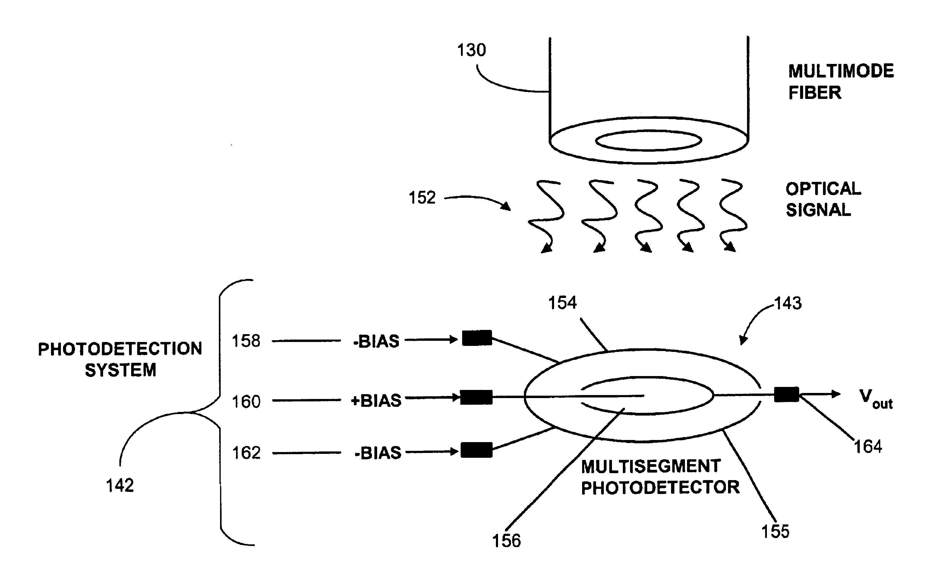
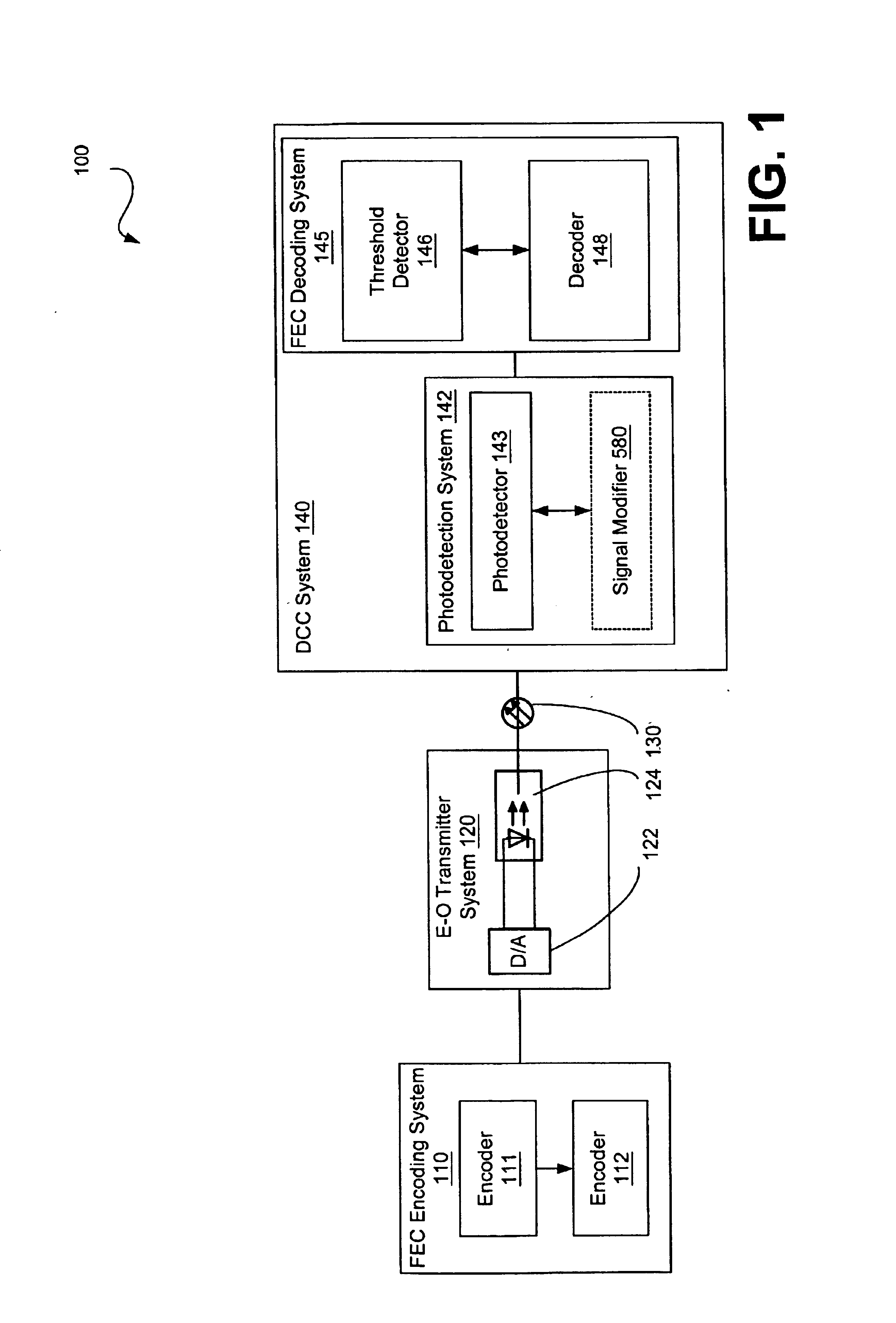
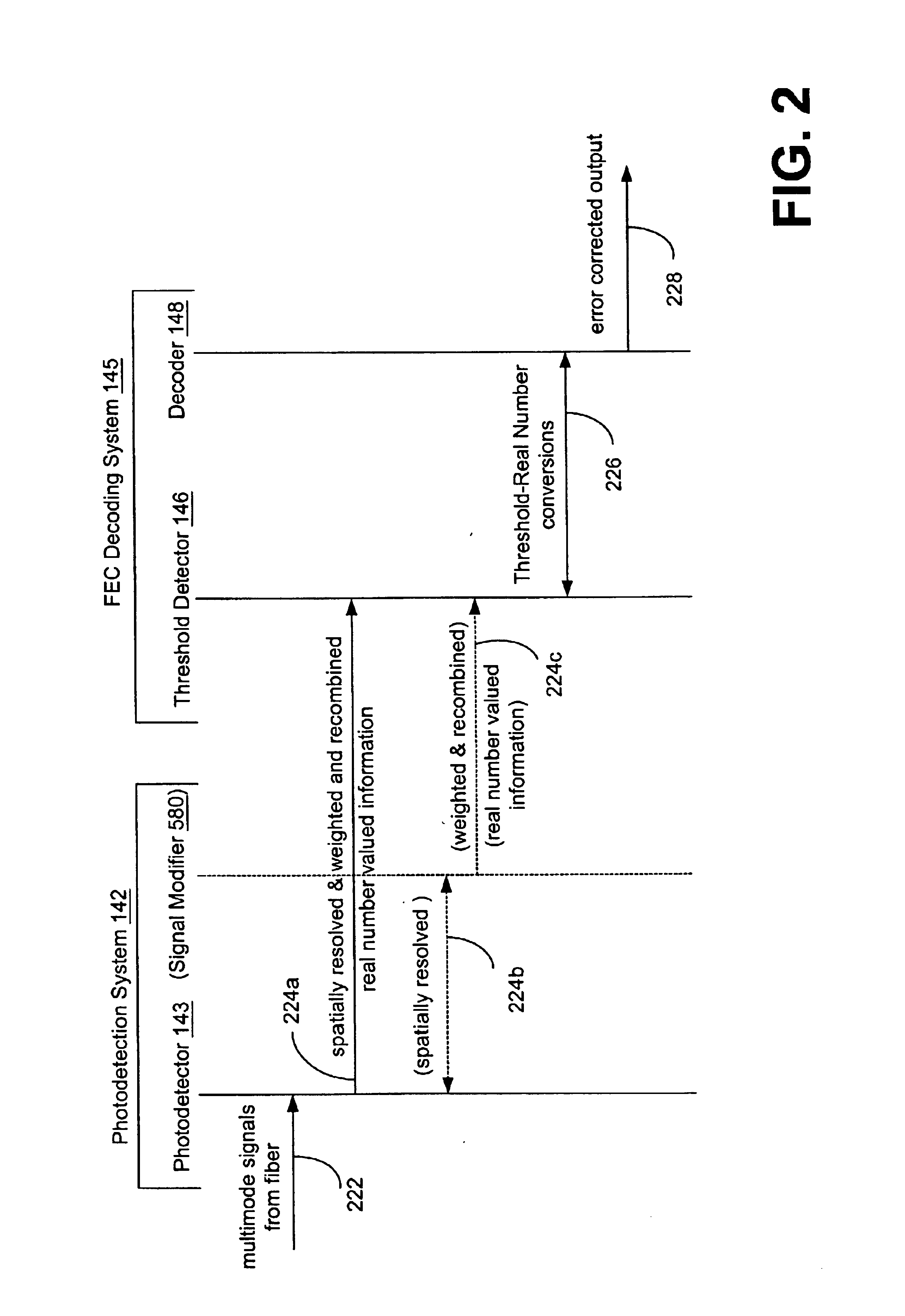
The preferred embodiments of the invention now will be described more fully hereinafter with reference to the accompanying drawings. One way of understanding the preferred embodiments of the invention includes viewing them within the context of an optical fiber communication system, and more particularly within the context of a system that includes functionality for photodetection, modal dispersion compensation, and / or error correction of a signal carrying information that is transferred over a multimode optical fiber communication system. This system, herein referred to as the detection-compensation-correction (DCC) system, preferably implements spatial resolution and equalization for detection and compensation of modal dispersion. The spatial properties of each mode (e.g., channels) delivered over the multimode fiber of the optical fiber communication system results in a spatial diversity of the temporal response within the emitted optical spot.

In one embodiment, a multisegmented ...


PUM


Abstract

A system is described that includes a system for correcting modal dispersion and errors in an optical fiber system. The system includes a multisegment photodetector coupled to an end of an optical fiber for detecting optical signals exiting the optical fiber and for converting the optical signals to an electrical output, the multisegment photodetector including a plurality of photodetector regions configured such that one of the plurality of photodetectors regions intercepts a mode in a manner distinct from another of the plurality of photodetectors. The system also includes logic configured to receive a resultant signal output from the photodetector regions and provide forward error correction decoding of the resultant signal.

Description

TECHNICAL FIELDThe present invention is generally related to optical fiber systems and, more particularly, is related to signal processing in multimode fiber links.BACKGROUND OF THE INVENTIONIn an optical communication system deploying a multi-mode fiber, an optical signal launched into the fiber propagates along the fiber as multiple modes, each of which exhibits a different group velocity. A portion of the source optical signal resides in the different modes. The multiple modes can have different arrival times at the end of the fiber. The different group velocities of the modes cause a pulse formed from more than one mode to spread out as it propagates, and is referred to as intermodal dispersion, which distorts the optical signal. Intermodal dispersion causes the optical signal initially launched through a fiber at a predetermined frequency and an initial phase to vary as a function of the length of the fiber.Modal dispersion reduces the maximum data transmission rate of the opti...

Claims


Application Information

Patent Timeline
Patent Type & Authority Patents(United States)
IPC IPC(8): G02B6/42H04B10/13H04B10/2581
CPCG02B6/4202H04B10/2581G02B6/4206
Inventor ARGON, CENKMCLAUGHLIN, STEVEN WILLIAMPATEL, KETANRALPH, STEPHEN E.
Owner GEORGIA TECH RES CORP
Why Eureka
Try Eureka