Three dimensional optical circuits

a three-dimensional optical circuit and optical circuit technology, applied in the direction of instruments, bundled fibre light guides, fibre mechanical structures, etc., can solve the problems of circuits that cannot be readily manufactured using conventional molding or forming techniques, and achieve the effects of eliminating optical signal losses, reducing optical signal loss, and being readily manufactured

Inactive Publication Date: 2005-01-25
3M INNOVATIVE PROPERTIES CO
View PDF42 Cites 24 Cited by
  • Summary
  • Abstract
  • Description
  • Claims
  • Application Information

AI Technical Summary

Benefits of technology

Although the equipment for carrying out SLA processes and other rapid prototyping techniques are relatively expensive machines, these systems are general purpose and are readily available. SLA machines and other rapid prototyping machines are readily programmable to create virtually any three dimensional object which can be designed on a computer aided design (“CAD”) system. Accordingly, the design of a three dimensional manifold for routing a large number of optical fibers may be laid out in any number of configurations or arrangements limited only to the capabilities of the CAD system or the imagination of the designer. Moreover, it is possible to program these systems to create passageways or channels for routing optical fibers to provide for an appropriate bend radius and thereby minimize optical signal loss, and to isolate and protect the individual fibers throughout the optical circuit. Further, it is possible to create optical circuits that could not be readily manufactured using conventional molding or forming techniques.
The fiber optic manifold, in accordance with the present invention, may take any number of possible embodiments, including a solid block having a number of hollow passageways connecting input points and output points or a large plurality of rigid hollow tubes which again have a number of input points and output points. By way of example only, these input openings may be arranged in a matrix having an equal number of rows and columns. In the case of 8 fiber optic cables each having 8 fibers, this would require an optical manifold having 64 input openings, 64 output openings, and 64 passageways connecting therebetween. If the input and output ends of the manifold are prope

Problems solved by technology

Further, it is possible to create optical circuits that could not be

Method used


Image

  • Three dimensional optical circuits
  • Three dimensional optical circuits
  • Three dimensional optical circuits

Examples


Embodiment Construction

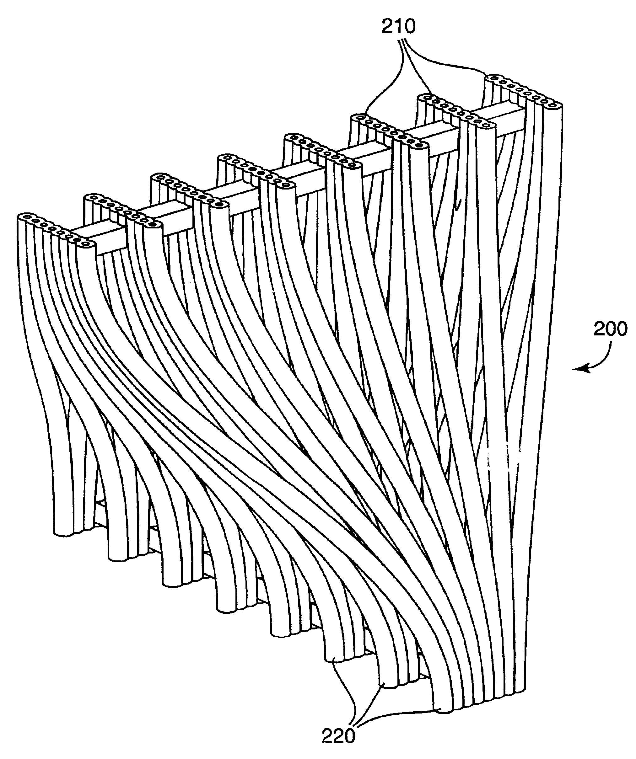
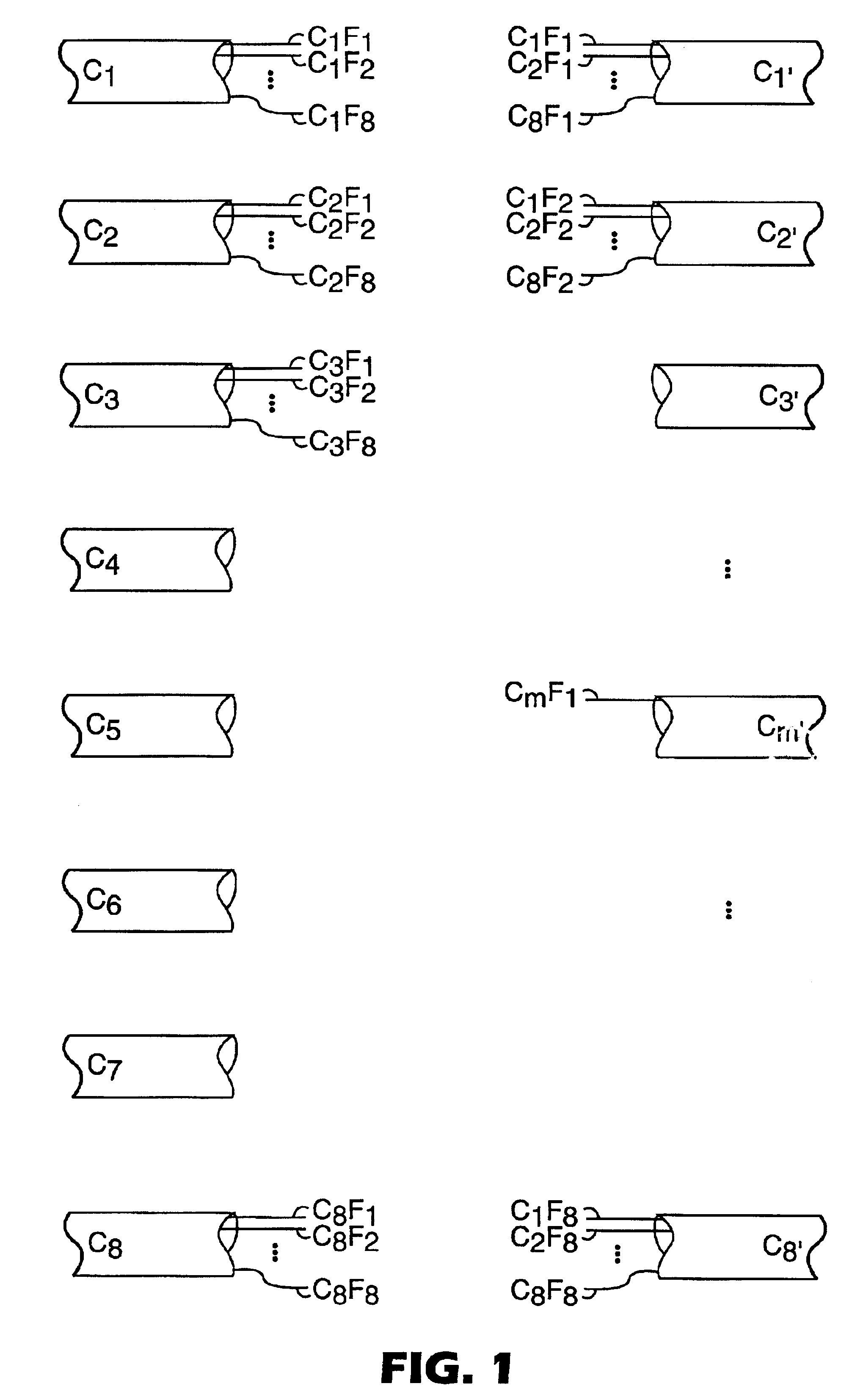
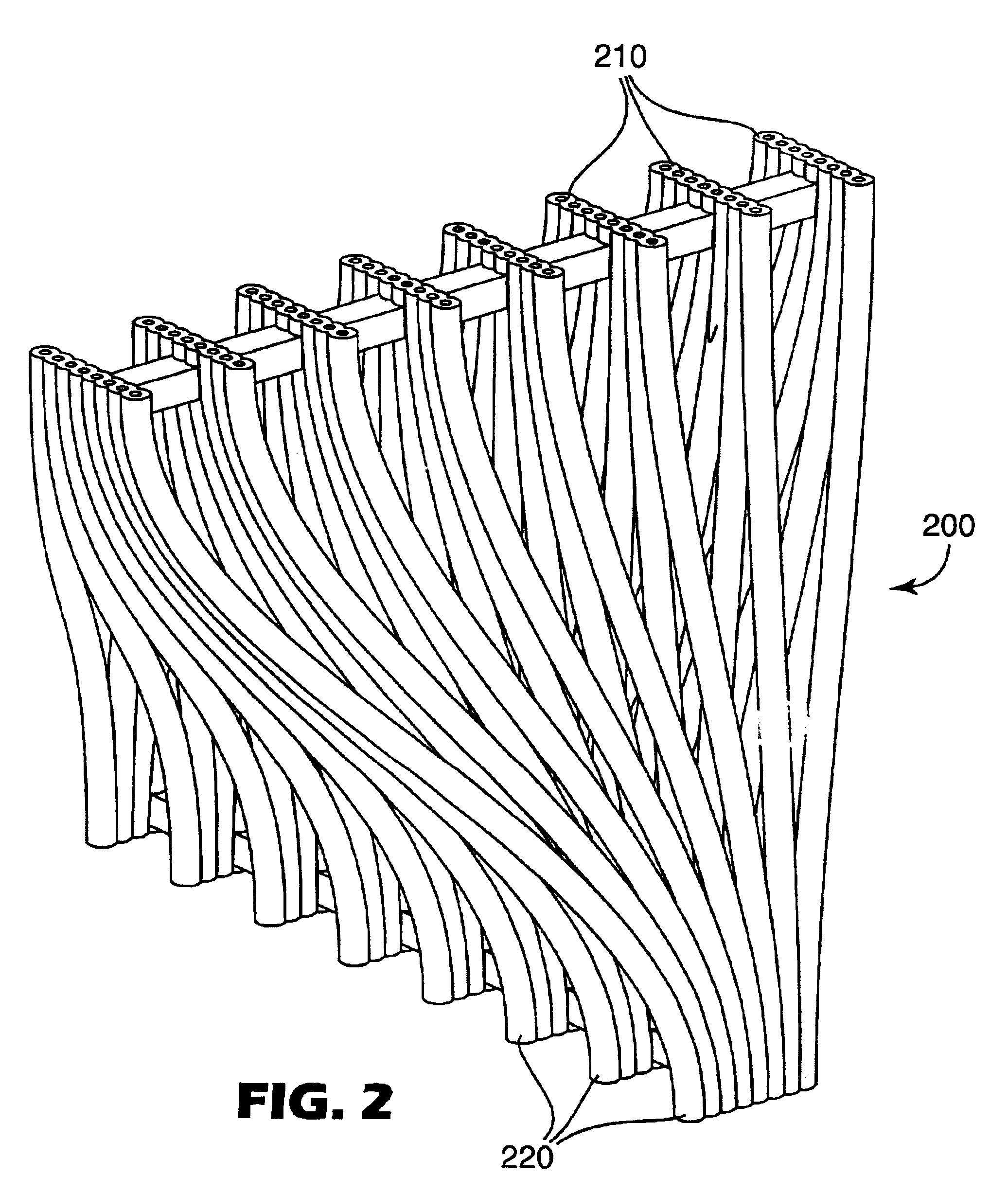
Referring now to the Figures, and in particular to FIGS. 2-6, there is disclosed a number of embodiments or variations constructed in accordance with the present invention for providing an optical manifold which may be incorporated into a three dimensional optical circuit such as a shuffle. As used herein, the term “optical manifold” shall refer to a component of a three dimensional optical circuit which provides a number of passageways for connecting a set of input openings to a set of output openings and for receiving a plurality of optical fibers in a first ordered arrangement at the input and outputting the plurality of fibers in a second ordered arrangement at the exit. As used in regard to the openings of an optical manifold, the term “ordered arrangement” refers not to the actual spatial relationship or location of one hole relative to another, but rather to the relationship of an input opening to an output opening.

By way of example only, an optical manifold for carrying out ...


PUM


Abstract

A three dimensional optical circuit featuring an optical manifold for organizing, guiding and protecting individual optical fibers is shown. One aspect of the present invention is a three dimensional manifold which may be constructed using a rapid prototyping process such as, but not limited to, stereolithography (“SLA”), fused deposition modeling (“FDM”), selective laser sintering (“SLS”), and the like. The manifold has a number of input openings in a first ordered arrangement at one end connected by passageways to a number of output openings in a second ordered arrangement at the opposite end. A plurality of optical fibers may be directed through the passageways of the manifold to produce a three dimensional optical circuit such as a shuffle. Moreover, the optical manifold may be used in conjunction with a number of connections or terminations to form a various optical modules. These modules may be configured for rack mounting within enclosures for electrical components.

Description

BACKGROUND OF THE INVENTION1. Field of the InventionThe present invention relates generally to three dimensional optical circuits and, more particularly, to a three dimensional optical circuit assembly comprising an optical manifold and a method for making the same.2. Background of the InventionOptical fiber networks are becoming increasingly common in modern telecommunications systems, high speed routers, computer systems and other systems for managing large volumes of data. Optical fiber networks typically comprise a large number of optical fibers which are routed over relatively long distances in order to increase transmission speeds and efficiencies relative to the propagation of conventional electrical signals. There is often the need to route individual optical fibers between various connection points throughout a system creating an “optical circuit”. One of the more common optical circuits in use today is referred to as an “optical shuffle”. By way of example only, a simple o...

Claims


Application Information

Patent Timeline
IPC IPC(8): G02B6/36G02B6/38G02B6/44
CPCG02B6/3636G02B6/3668G02B6/4472G02B6/3807G02B6/3825G02B6/3878G02B6/3684G02B6/3608G02B6/3676G02B6/368G02B6/3885G02B6/3897B33Y80/00G02B6/46
Inventor SIMMONS, RICHARD L.SHOEMAKER, CURTIS L.
Owner 3M INNOVATIVE PROPERTIES CO
Why Eureka
Try Eureka