Method of manufacturing an edge reflection type surface acoustic wave device

a technology of surface acoustic wave and reflection, which is applied in the direction of magnets, instruments, magnets, etc., can solve the problems of cracks on the end surfaces, deviation of gdt (group delay time characteristics), and unsatisfactory ripples in characteristics

Inactive Publication Date: 2005-02-01
MURATA MFG CO LTD
View PDF9 Cites 4 Cited by
  • Summary
  • Abstract
  • Description
  • Claims
  • Application Information

AI Technical Summary

Benefits of technology

In order to overcome the problems described above, preferred embodiments of the present invention provide a method of manufacturing an edge reflection type surface acoustic wave device in which the above-described defects in the prior art are solved, the degradation of characteristics due to the reflection of unnecessary waves on the end surfaces is prevented from occurring, and cracks and chipping are prevented from occurring, and also provide an edge reflection type surface acoustic wave device produced by such a method of manufacturing.

Problems solved by technology

In the edge reflection type surface acoustic wave device, the SH wave is reflected between the opposing two end surfaces, and, in this case, there is a problem that, when unnecessary waves other than the SH waves are reflected at the end surfaces, undesired ripples appear in the characteristics and the deviation of GDT (group delay time characteristics) increases.
However, when two opposing end surfaces of a piezoelectric substrate are cut by using a blade under the condition that the end surfaces become a rough surface, there is a problem in that cracks are produced on the end surfaces and in that chipping is likely to occur in the edge portion between the end surface and the bottom surface of the piezoelectric substrate.
That is, it is very difficult to obtain an edge reflection type surface acoustic wave device in which ripples and spurious noise are fully suppressed and cracks, chipping, etc., are not produced.

Method used


Image

  • Method of manufacturing an edge reflection type surface acoustic wave device
  • Method of manufacturing an edge reflection type surface acoustic wave device
  • Method of manufacturing an edge reflection type surface acoustic wave device

Examples


Embodiment Construction

Hereinafter, specific preferred embodiments of the present invention are described with reference to the drawings in order to make the present invention clear.

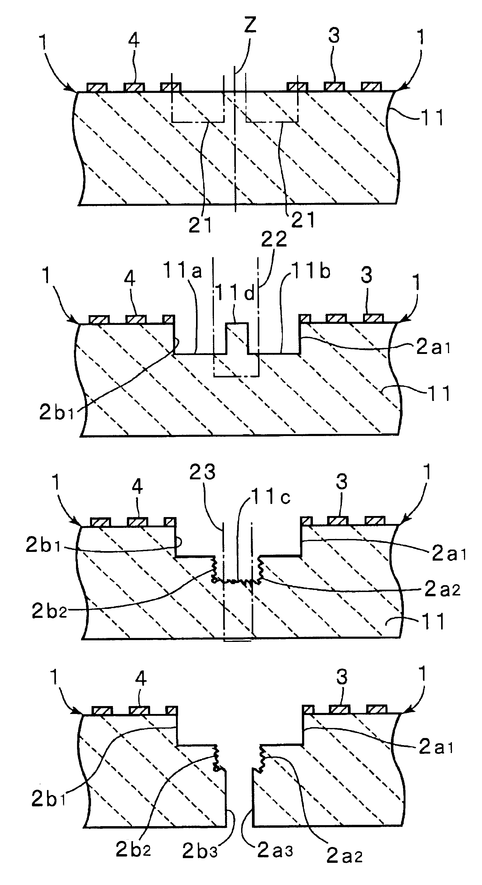
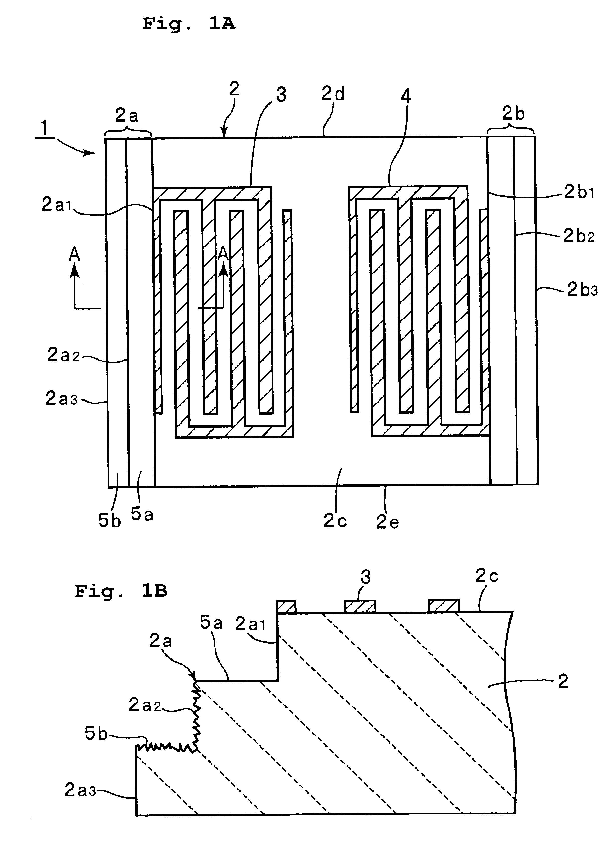
FIG. 1A is a top view of an edge reflection type surface acoustic wave device obtained by a manufacturing method for an edge reflection type surface acoustic wave device according to a preferred embodiment of the present invention, and FIG. 1B is a partially enlarged sectional front view taken on line A—A of FIG. 1A.

An edge reflection type surface acoustic wave device 1 preferably includes a piezoelectric substrate 2. The piezoelectric substrate 2 is preferably a substantially rectangular plate and has end surfaces 2a and 2b which are opposed to each other.

The piezoelectric substrate 2 is preferably made of a piezoelectric single crystal such as LiTaO3, LiNbO3, quartz, or other suitable material, or piezoelectric ceramics such as titanate zirconate lead ceramics. IDTs 3 and 4 are disposed on the upper surface of the piezoelect...


PUM

PropertyMeasurementUnit
depthaaaaaaaaaa
thicknessaaaaaaaaaa
group delay time characteristicsaaaaaaaaaa

Abstract

A method of manufacturing an edge reflection type surface acoustic wave device using a Shear Horizontal type surface acoustic wave includes the steps of making a first half cut defining a first end surface portions having a smooth surface, that is, opposing two end surfaces which function as reflection end surfaces, from the upper surface of a piezoelectric substrate after at least one of a plurality of IDTs has been formed on the upper surface of the piezoelectric substrate, making a second half cut for forming second end surface portions having a rough surface after making the first cut, and making a full cut for cutting the piezoelectric substrate so as to reach the lower surface of the piezoelectric substrate outside of the second end surface portions in the surface acoustic wave propagation direction.

Description

BACKGROUND OF THE INVENTION1. Field of the InventionThe present invention relates to a surface acoustic wave device used for resonators and bandpass filters and more particularly, to an edge reflection type surface acoustic wave device having a construction in which a Shear Horizontal (SH) type surface acoustic wave is reflected between two opposing end surfaces and a manufacturing method for the same.2. Description of the Related ArtVarious edge reflection type surface acoustic wave devices using of SH waves such as a BGS wave, a lobe wave, etc., reflected between confronting end surfaces have been proposed.In the edge reflection type surface acoustic wave device, the SH wave is reflected between the opposing two end surfaces, and, in this case, there is a problem that, when unnecessary waves other than the SH waves are reflected at the end surfaces, undesired ripples appear in the characteristics and the deviation of GDT (group delay time characteristics) increases.In Japanese Une...

Claims


Application Information

Patent Timeline
Patent Type & Authority Patents(United States)
IPC IPC(8): H03H9/02H03H3/08H03H9/25
CPCH03H9/02629H03H9/02669H03H9/02677H03H3/08Y10T29/42Y10T29/49007Y10T29/49005Y10T29/49135Y10T29/4908Y10T29/49133Y10T83/0319Y10T83/0215Y10T83/0222H03H9/25
Inventor KURATANI, YASUHIROMUKAI, TAKAOMIYATA, TOMOYASUYOSHIKAWA, HIDEHARU
Owner MURATA MFG CO LTD
Why Eureka
Try Eureka