Actuating valve for bidirectional pneumatic cylinder and use of such actuating valve for bobbin creels controlled by pneumatic cylinders

a technology of pneumatic cylinder and actuating valve, which is applied in the direction of servomotors, manufacturing tools, shuttles, etc., can solve the problems of sealing problems between the individual valve channels

Inactive Publication Date: 2005-02-01
ZHUOLANG INTELLIGENT MACHINERY CO LTD
View PDF10 Cites 17 Cited by
  • Summary
  • Abstract
  • Description
  • Claims
  • Application Information

AI Technical Summary

Benefits of technology

The invention has the object to provide an actuating valve which does not have the disadvantages which are caused, in particular, by employing a 5 / 3 port sliding valve.
A basic principle of the invention resides in that two 3 / 2 port directional control valves are employed in place of the previously employed 5 / 3 port sliding valve so that the sealing problems are significantly reduced.
According to a further embodiment of the invention, it is proposed that, overall, slide valves are no longer employed for any of the valve units and, instead, so-called seat valves are used. An actuating valve according to the second embodiment is characterized in particular by its compact configuration thus facilitating its manipulation.

Problems solved by technology

In particular, when employing a 5 / 3 port sliding valve, this causes sealing problems between the individual valve channels as a result of the significant number of required lip seals.

Method used


Image

  • Actuating valve for bidirectional pneumatic cylinder and use of such actuating valve for bobbin creels controlled by pneumatic cylinders
  • Actuating valve for bidirectional pneumatic cylinder and use of such actuating valve for bobbin creels controlled by pneumatic cylinders
  • Actuating valve for bidirectional pneumatic cylinder and use of such actuating valve for bobbin creels controlled by pneumatic cylinders

Examples


Embodiment Construction

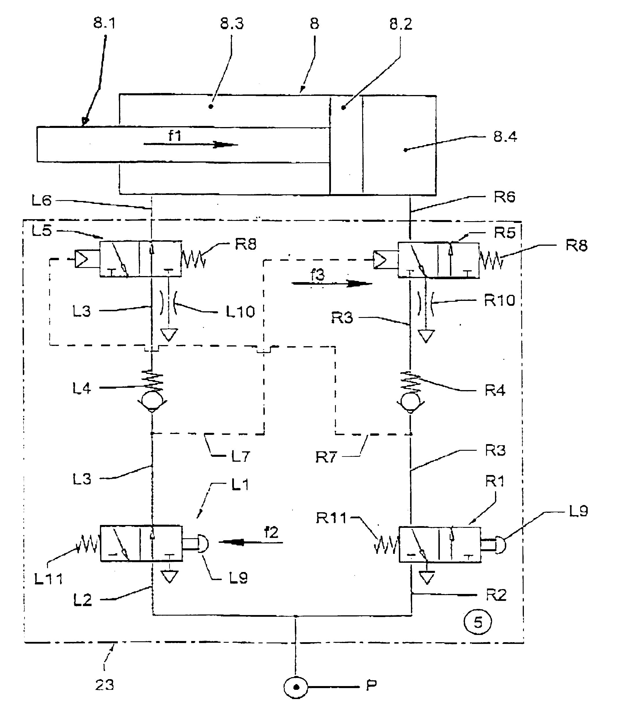
FIG. 2 shows a bidirectionally acting pneumatic cylinder 8 with compressed air lines L6, R6, connected to an actuating valve 23, opening on the opposite ends. A piston (not illustrated) mounted on the piston rod 8.1 can be loaded with compressed air by means of the compressed air connecting line L6 or R6 while the opposed cylinder chamber or pressure chamber can be vented via the other line R6 or L6. On the pneumatic cylinder 8 a drag bearing 24 is provided. A further drag bearing 25 is mounted on the piston rod 8.1 in order to connect the pneumatic cylinder to two machine parts which are movable relative to one another.

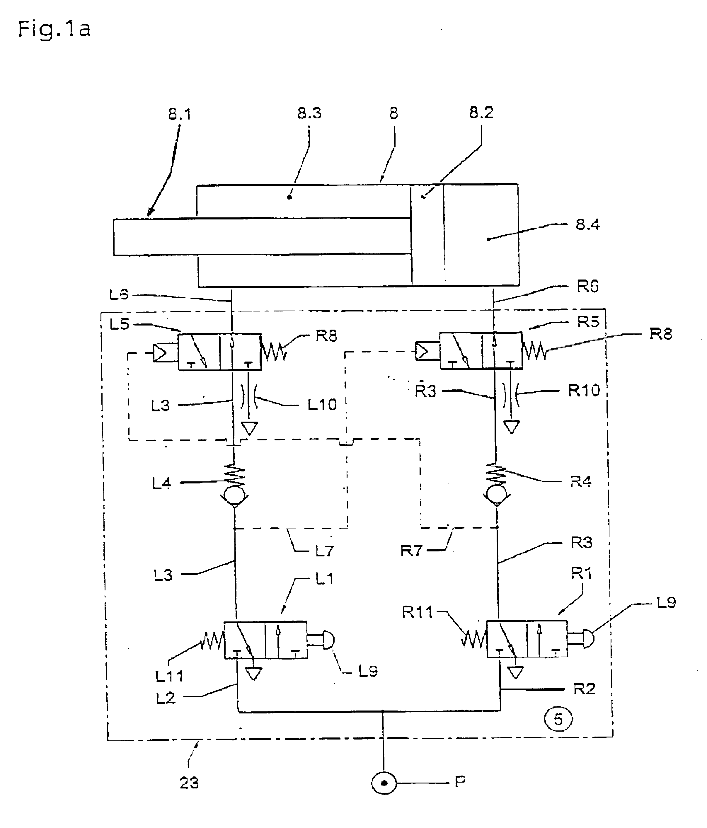
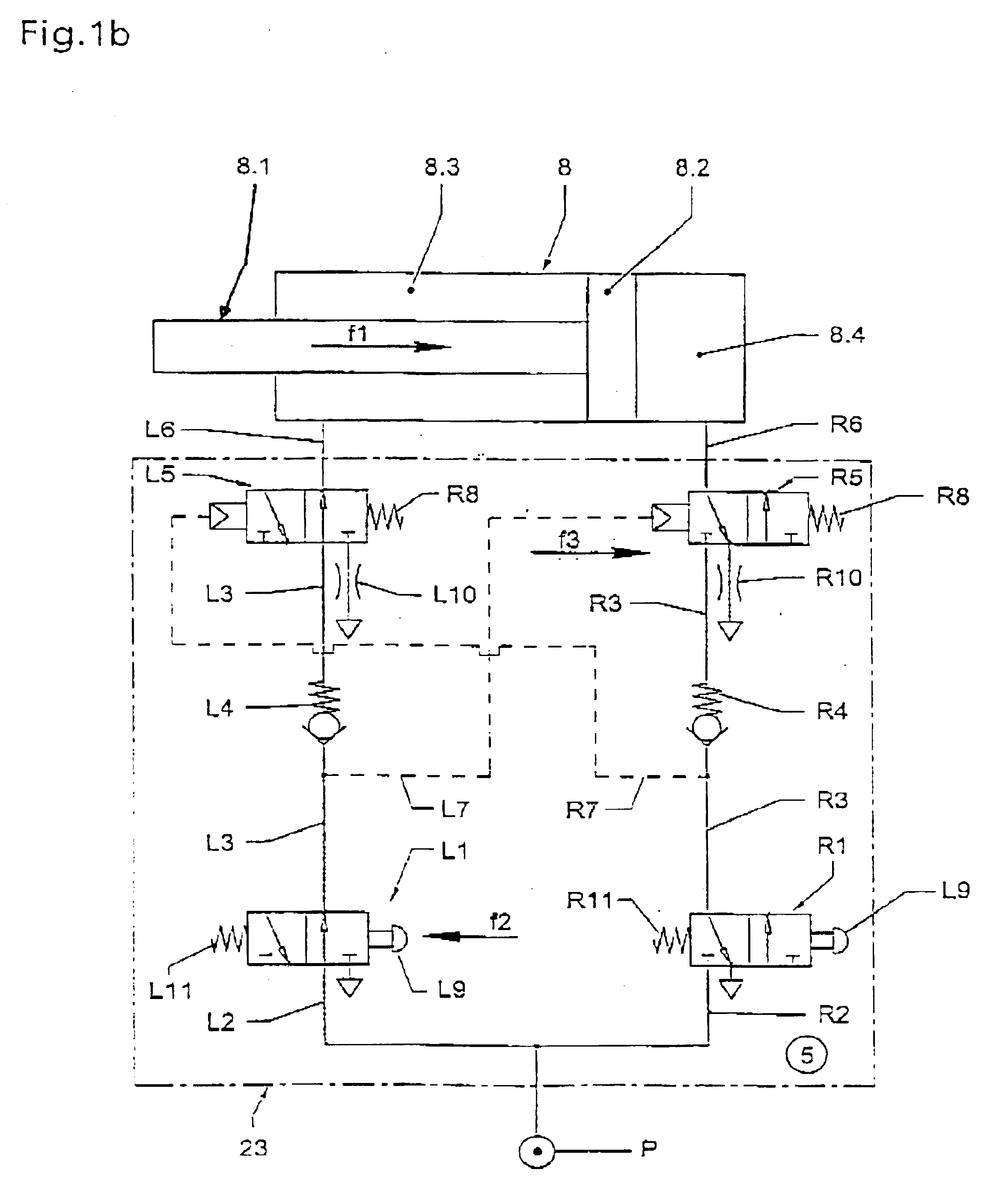
FIG. 1a shows the actuating valve 23 in the rest position; FIG. 1b shows an operating position in which the piston rod 8.1 is being retracted in the direction of arrow f1 into the cylinder 8.

According to FIG. 1a, two relay valves in the form of, for example, manually actuated 3 / 2 port directional control valves L1, R1, are connected by means of connecting lines L2, R...


PUM


Abstract

An actuating valve has two relay valves connected to a compressed air source and a pneumatic cylinder with two pressure chambers. When one relay valve is actuated, one pressure chamber is pressure-loaded and the other is relieved. Two 3 / 2 port directional control valves are arranged upstream of the pneumatic cylinder. Two check valves are positioned in branch lines connecting the relay valves and the directional control valves. A control line connects the branch line to the other directional control valve, respectively. The directional control valves are moveable between a first position allowing compressed air to pass and a pressure relief position. When the relay valves are inactive, the directional control valves are in the first position and the relay valves are in a venting position for the branch lines. When one relay valve is actuated, it assumes a position allowing passage of air to the branch line connected to it.

Description

BACKGROUND OF INVENTIONThe invention relates to an actuating valve pneumatic cylinder comprising two pressure chambers separated from one another by a piston connected on a piston rod, which actuating valve comprises two 3 / 2 port directional control valves as relay valves connectable to a compressed air source and further comprises a valve system connected between these directional control valves and the pneumatic cylinder by which upon actuation of one of the two relay valves one of the pressure chambers can be loaded with compressed air and the other pressure chamber can be relieved of pressure via a venting throttle, respectively.It is required in connection with such an actuating valve that after release of the respectively actuated relay valve, the pneumatic cylinder or its piston remains loaded with compressed air on both ends, that upon release of the previously actuated valve no further venting or pressure relief of both pressure chambers occurs, but that instead a positiona...

Claims


Application Information

Patent Timeline
Patent Type & Authority Patents(United States)
IPC IPC(8): F15B11/00B65H49/16
CPCB65H49/16F15B11/003B65H2701/31F15B2211/30505F15B2211/3051F15B2211/3057F15B2211/7107F15B2211/327F15B2211/329F15B2211/353F15B2211/40507F15B2211/46F15B2211/31576
Inventor LOHMANN, RALFHEINEN, GEORGZISCHEWSKI, JORG
Owner ZHUOLANG INTELLIGENT MACHINERY CO LTD
Why Eureka
Try Eureka