Self-aspirating high-area-ratio inter-turbine duct assembly for use in a gas turbine engine

a gas turbine engine and high-area-ratio technology, which is applied in the direction of machines/engines, stators, efficient propulsion technologies, etc., can solve the problems of weak adverse pressure gradients along the configuration, gas turbine engine performance may suffer, and either configuration is problematic, so as to achieve enhanced aerodynamic benefits and optimize the performance of gas turbine engines

Inactive Publication Date: 2005-02-08
GENERAL ELECTRIC CO
View PDF4 Cites 86 Cited by
  • Summary
  • Abstract
  • Description
  • Claims
  • Application Information

AI Technical Summary

Benefits of technology

In a still further embodiment of the present invention, a method for optimizing the performance of a gas turbine engine or the like includes, given a primary fluid flow through an inter-turbine duct of the gas turbine engine, diverting a predetermined portion of the primary fluid flow into a bypass channel. The method also includes transmitting the predetermined portion of the primary fluid flow to a low-pressure turbine nozzle of the gas turbine engine. The method further includes expelling the predetermined portion of the primary fluid flow into the interior of the low-pressure turbine nozzle. The method still further includes distributing the predetermined portion of the primary fluid flow along the suction side of the low-pressure nozzle and expelling it for enhanced aerodynamic benefit of the low-pressure nozzle.

Problems solved by technology

Given conventional systems, assemblies, and methods, either configuration is problematic.
If the slope of the outer-body surface of the inter-turbine duct is relatively steep, strong adverse pressure gradients may be created along the outer-body surface and boundary layer separation may occur in the inter-turbine duct.
As a result, gas turbine engine performance may suffer.
If the length of the outer-body surface of the inter-turbine duct is relatively long, extra weight is added to the gas turbine engine and, again, performance may suffer.
Thus, conventional gas turbine engines typically use non-optimal inter-turbine ducts that are relatively long and that have outer-body surfaces with a relatively shallow slope.

Method used


Image

  • Self-aspirating high-area-ratio inter-turbine duct assembly for use in a gas turbine engine
  • Self-aspirating high-area-ratio inter-turbine duct assembly for use in a gas turbine engine
  • Self-aspirating high-area-ratio inter-turbine duct assembly for use in a gas turbine engine

Examples


Embodiment Construction

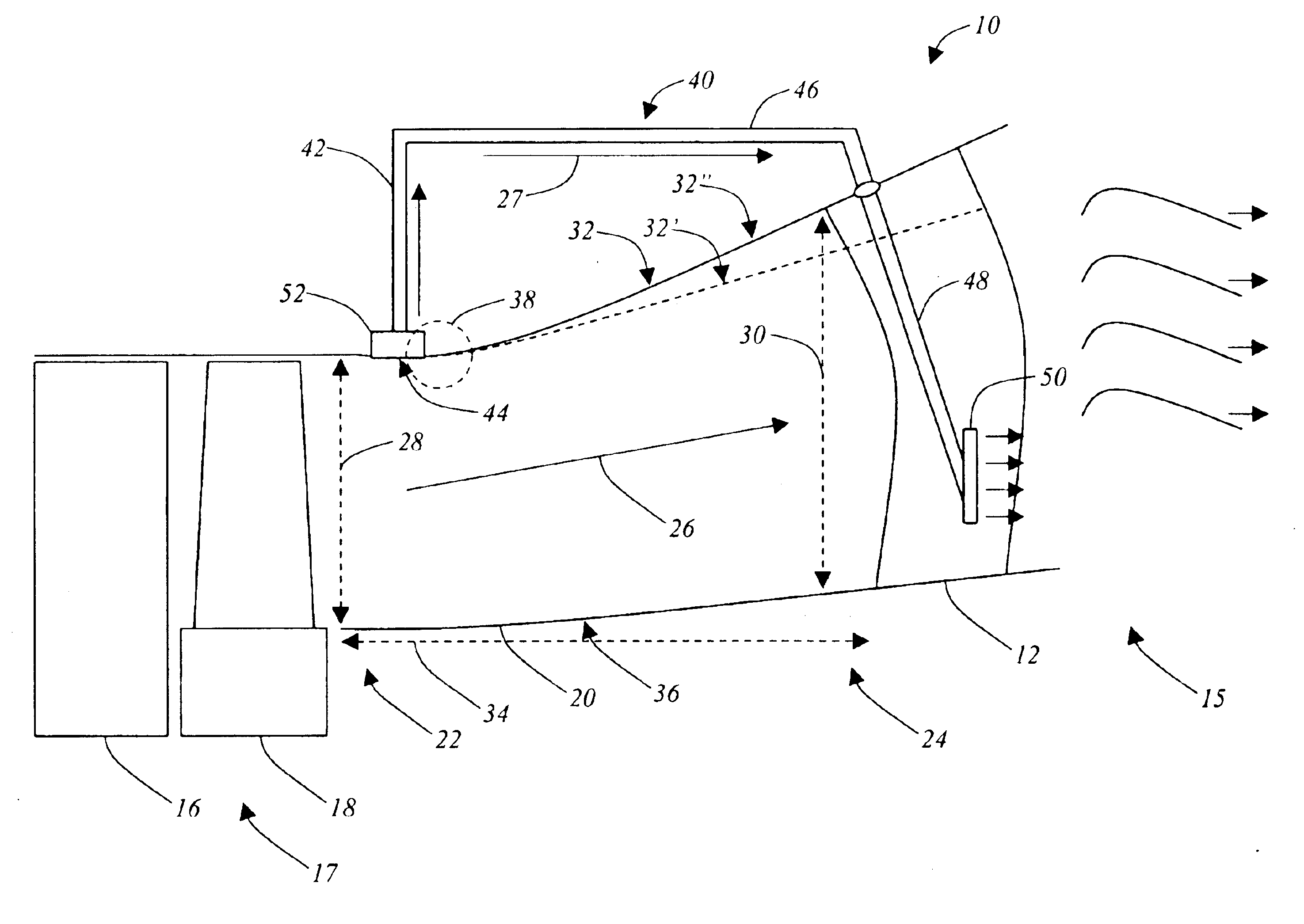
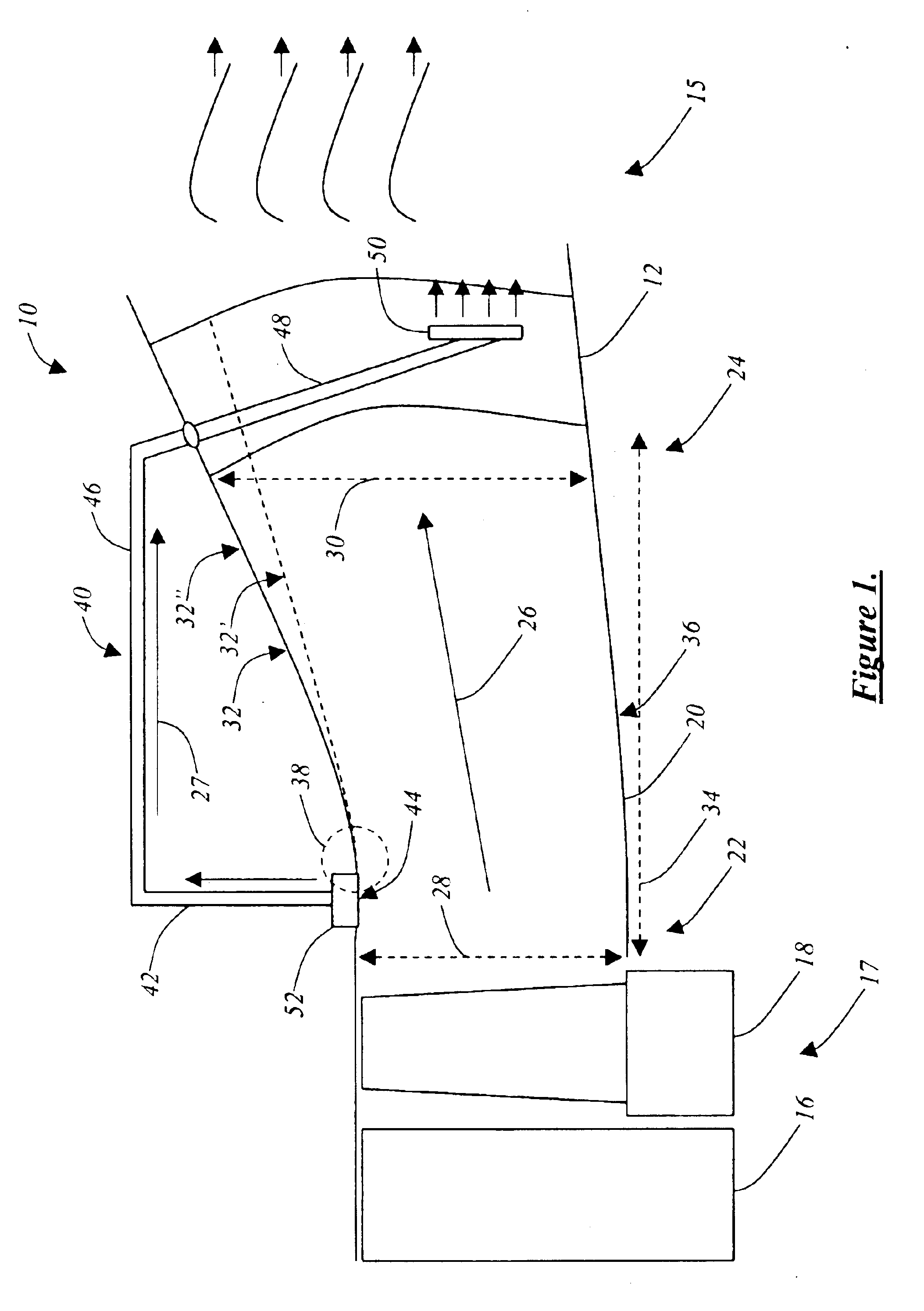
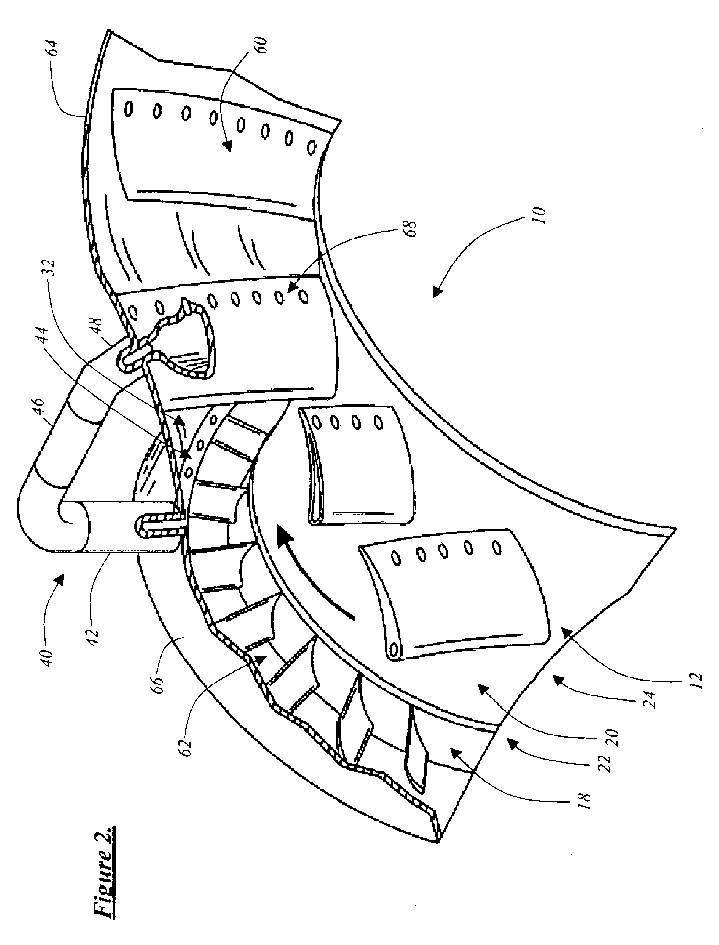
The systems, assemblies, and methods of the present invention use boundary layer suction on the outer-body surface of the inter-turbine duct of a gas turbine engine or the like to minimize the creation of adverse pressure gradients and prevent boundary layer separation along the outer-body surface which would otherwise limit the performance of the gas turbine engine. This allows for the use of a relatively large diameter low-pressure turbine spool, including a low-pressure turbine nozzle and an associated low-pressure turbine rotor. The low pressure required to produce the boundary layer suction is obtained from the suction side of the low-pressure turbine nozzle. Establishing a fluid flow path between these points allows for self-aspiration. Advantageously, the fluid flow ejected at the suction side of the low-pressure turbine nozzle may be used to control boundary layer separation on the diffusing side of the low-pressure turbine nozzle. This fluid flow control allows for the use ...


PUM


Abstract

In various embodiments, the present invention provides a means for improving gas turbine engine performance by applying fluid flow control to the inter-turbine duct joining a high-pressure turbine spool and an associated low-pressure turbine spool, allowing the low-pressure turbine spool to have a relatively larger diameter than the high-pressure turbine spool. One or more unobstructed fluid flow paths between one or more boundary layer suction ports disposed within the upstream end of the outer-body surface of the inter-turbine duct and the suction side of the associated low-pressure turbine nozzle are provided. Advantageously, the natural static pressure difference between these points results in a self-aspirating assembly. The fluid flow control provided by the respective suction and blowing forces generated allows for a relatively larger diameter low-pressure turbine spool and/or relatively fewer low-pressure turbine nozzles to be used than is possible with conventional systems, assemblies, and methods. Thus, a gas turbine engine weight savings and optimized performance may be achieved.

Description

FIELD OF THE INVENTIONThe present invention relates generally to the field of gas turbine engines. More specifically, the present invention relates to a self-aspirating high-area-ratio inter-turbine duct assembly for use in a gas turbine engine or the like operable for generating thrust and / or power.BACKGROUND OF THE INVENTIONAs is known to those of ordinary skill in the art, there is a preferred ratio between the diameter of the high-pressure turbine spool (including the high-pressure turbine nozzle and the associated high-pressure turbine rotor) and the diameter of the associated low-pressure turbine spool (including the low-pressure turbine nozzle and the associated low-pressure turbine rotor) in a gas turbine engine, with the low-pressure turbine spool having a relatively larger diameter than the high-pressure turbine spool. As described herein below, this ratio provides optimal gas turbine engine performance. However, in order to achieve this preferred ratio, the slope of the o...

Claims


Application Information

Patent Timeline
Patent Type & Authority Patents(United States)
IPC IPC(8): F01D9/00F01D5/14F01D9/06F01D9/02F01D9/04F01D17/10F01D25/30F02C9/18
CPCF01D5/145F01D9/041F01D9/06F01D17/105F02C9/18F01D25/305Y10S415/914F05D2270/17Y02T50/671Y02T50/673Y02T50/60
Inventor KIRTLEY, KEVINGRAZIOSI, PAOLO
Owner GENERAL ELECTRIC CO
Why Eureka
Try Eureka