Ring joint, connection structure for connecting piping and ring joint, and method of connecting ring joint and piping

Inactive Publication Date: 2005-02-08
USUI KOKUSAI SANGYO KAISHA LTD
View PDF21 Cites 10 Cited by
  • Summary
  • Abstract
  • Description
  • Claims
  • Application Information

AI Technical Summary

Benefits of technology

By forming and fixing the branch pipe to the piping, the piping and the branch pipe are connected firmly having a highly reliable gas-tightness at the connecting portion therebetween. The disengagement prevention means capable of preventing disengagement between the branch pipe and the piping with a highly reliable disengagement resistance can be provided by burying the annular protruded portion of the piping into the resin of the piping.
In the second process, the branch pipe is contacted and disposed upon the resin welding surface of the ring joint body in a direction perpendicularly intersecting with the axial core of the fitting hole of the eyebolt and in communication with the flow path. Applying the welding means to the contacting portion allows the branch pipe to fixedly welded to the side surface of the ring joint body, thereby completing the connection between the ring joint and the piping via the branch pipe. Accordingly, the ninth and tenth inventions enables a safe and easy connection process between the ring joint and the piping and provides a connection structure having highly reliable gas-tightness and disengagement resistance.
Subsequent to fixedly welding the ring joint body and the branch pipe in the ninth and tenth inventions,

Problems solved by technology

Conventionally, processing the ring joint and connecting the ring joint with the piping, however, requires a complicated technique of skillful work, numerous manufacture steps and expensive manufacture cost.
With the prior art, no brazing procedure for connecting the ring joint and the piping is required, a rust-proofed piping can be employed, and neither the work environment or the human body will be adversely aff

Method used


Image

  • Ring joint, connection structure for connecting piping and ring joint, and method of connecting ring joint and piping
  • Ring joint, connection structure for connecting piping and ring joint, and method of connecting ring joint and piping
  • Ring joint, connection structure for connecting piping and ring joint, and method of connecting ring joint and piping

Examples


first embodiment

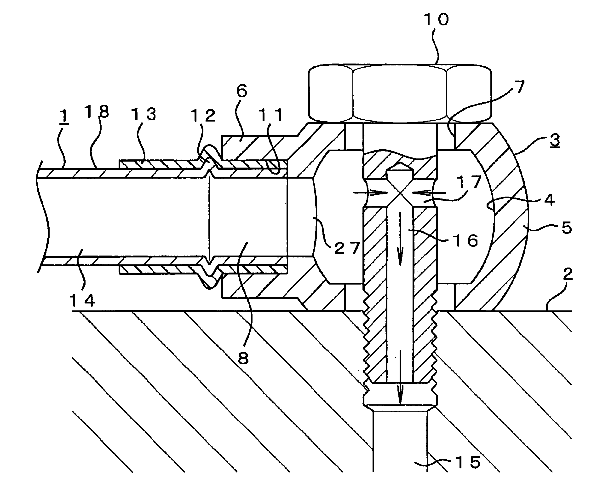
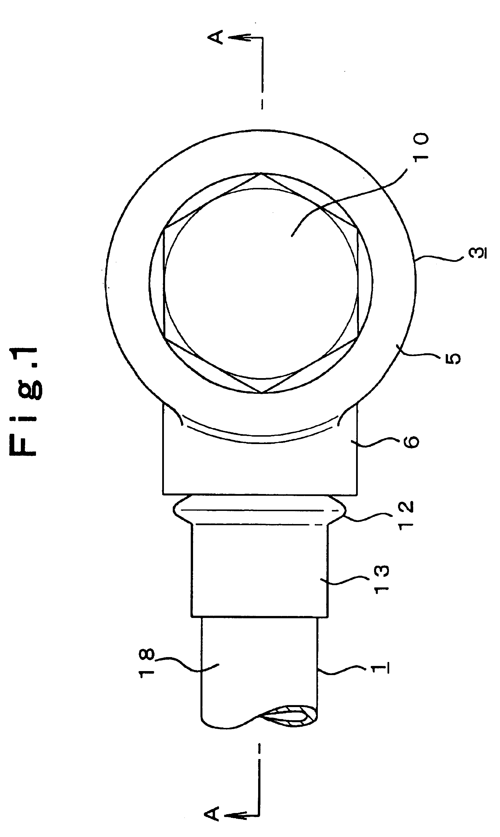
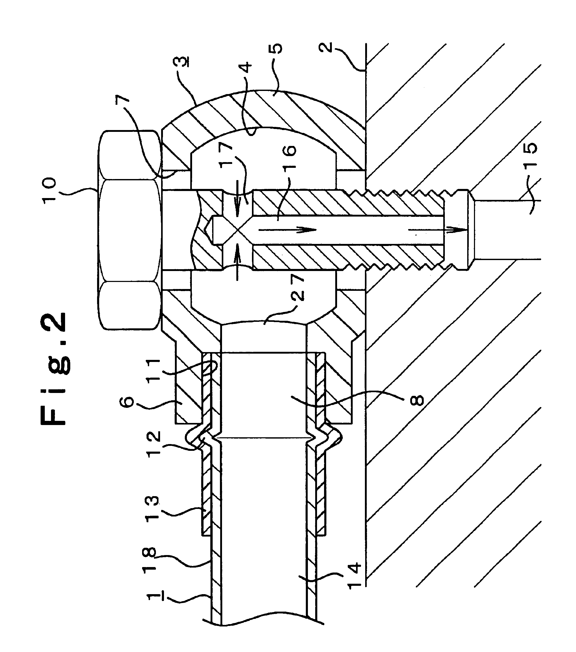
The first embodiment will hereinafter be described in detail with reference to FIG. 1 and FIG. 2. Numeral 1 is a metal piping disposed at an floor panel, a front face panel or the like, which includes, for example, a fuel main pipe for supplying fuel from an fuel tank to an engine room, a fuel return pipe for returning surplus fuel from an engine to a fuel tank, an evaporation piping for enabling fuel vapor inside a fuel tank to adhere to a canister inside an engine room, a vacuum piping manipulating negative pressure of intake, an oil pipe, etc. The piping 1 is branched in a direction perpendicularly intersecting with the base member serving to flow fuel, air, or lubricants or the like for automobiles, and arranged to a side of the above-mentioned panel.

A connection structure and a connection method using a ring joint for connecting the piping 1 and the base member 2 in a branched and perpendicularly intersecting manner, are described in detail hereinafter. As shown in FIG. 1 and F...

ninth embodiment

The ninth embodiment will hereinafter be explained with reference to FIG. 11 and FIG. 12. Although the piping 1 in the eighth embodiment has a substantially equal outer diameter from the tip thereof to the annular protruded portion 25, the piping 1 of the ninth embodiment has a tip side thereof with a narrowed diameter, in which the tapered pipe tip portion 30 has a tip thereof formed with a minimal diameter. In correspondence to the tapered pipe tip portion 30, the inner peripheral surface 11 of the cohering portion 32 of the branch pipe 6 has the tapered inner peripheral surface 28 formed thereto. The positioning between the tip side of the insertion portion 8 and the cohering portion 32 as well as the positioning between the annular protruded portion 25 and the engagement nail 35 can be performed easily and more accurately by inserting the tapered pipe tip portion 30 into the tapered inner peripheral surface 28. After the piping 1 is completely inserted, the inner peripheral surf...


PUM


Abstract

Connection structure for connecting a piping used in automobiles or the like to a ring joint for providing highly reliable gas-tightness. The ring joint includes a ring joint body including a fitting hole for an eyebolt, the fitting hole being piercingly formed in an axial core portion of the ring joint body and in continuation from an annular recessed groove formed inside the ring joint body, and a flow path extending in a direction perpendicular to and intersecting with the fitting hole. A branch pipe is formed as a unitary body with the ring joint body and arranged in a direction perpendicular to and intersecting with the eyebolt. A piping for insertion into the branch pipe has an outer peripheral surface covered with resin, and the resin of the outer peripheral surface of the piping and an inner peripheral surface of the branch pipe are fixedly welded to one another.

Description

BACKGROUND OF THE INVENTION1. Field of the InventionThis invention relates to a ring joint for attaching a piping used in automobiles, various machines, and apparatuses, etc. to a base member in a perpendicularly intersected manner; a connection structure for connecting a ring joint and a piping; and a method of connecting a ring joint and a piping; by which the ring joint and the piping can be connected inexpensively with a simple connecting method, a highly reliable gas-tightness and disengagement resistance can be obtained, and the ring joint can be formed easily.2. Description of Related ArtConventionally, a metal ring joint is generally used as a joint in connecting a piping used for automobiles, various machines and apparatuses (more particularly, for flowing fuel, air, lubricants or the like used in automobiles) to a base member in a perpendicularly intersecting manner when arranging the piping to a floor panel or a front panel or the like. The ring joint, for example, has a ...

Claims


Application Information

Patent Timeline
IPC IPC(8): F16L41/00F16L41/02
CPCF16L41/005F16L41/02
Inventor USUI, MASAYOSHIYOTSUMOTO, SHU
Owner USUI KOKUSAI SANGYO KAISHA LTD
Why Eureka
Try Eureka