Sliding reconstitution device with seal

a reconstitution device and sealing technology, applied in the direction of pharmaceutical containers, packaging goods, packaged foodstuffs, etc., can solve the problems of difficult maintenance of sterile conditions, time-consuming reconstitution procedure, toxic,

Inactive Publication Date: 2005-02-08
BAXTER INT INC
View PDF443 Cites 179 Cited by
  • Summary
  • Abstract
  • Description
  • Claims
  • Application Information

AI Technical Summary

Benefits of technology

In another embodiment, the coupling device includes a means for preventing the first sleeve member from becoming disassociated from the second sleeve member. In a more preferred embodiment, the second sleeve member forms a channel for the first sleeve member and slidingly receives the first sleeve member. A bushing having a diameter greater than that of the second sleeve member is connected to the proximal end of the first sleeve member, preventing it from becoming disassociated when being moved from the inactivated position to the activated position.

Problems solved by technology

Reconstituting the drug presents a number of problems.
The reconstitution procedure is time consuming and requires aseptic technique.
In some procedures for reconstituting, maintaining sterile conditions is difficult.
Moreover, some drugs, such as chemotherapy drugs, are toxic and exposure to the medical personnel during the reconstitution procedure can be dangerous.
However, no seal was provided on the opposite end of the connector, so the vial and device assembly had to be used relatively quickly after connection or stored in a sterile environment, such as under a hood.
Also, the '209 Patent does not disclose any structure for preventing the device from becoming inadvertently disassembled when being moved to the activated position.
This would require the medical personnel to either reassemble the device, or, potentially, dispose of it due to contamination.
The device described in the '209 Patent, also does not provide a visual indication that the device is in the activated position.
This could cause coring of the vial stopper which could lead to leakage of the vial stopper.
Additionally it was possible for a vial to be misaligned while being attached to the device, causing the attachment process to be difficult for medical personnel.
Removal of the vial could remove all evidence that the reconstitution step had occurred and, possibly, lead to a second unintended dosage of medicine being administered.
However, tamper evident marks may not be left in vials that have a cap that is too short to impinge upon the sharp points.
This is undesirable, as it initiates the time period in which the drug must be used, and typically this is a shorter period relative to the normal shelf-life of the drug product.
The '020 device also does not provide a structure for preventing a docked vial from rotating relative to the spike 25.
A closure of the vial can become damaged or cored upon rotation, which in turn, can lead to particles from the closure from entering the fluid that eventually passes to a patient.
It can also lead to leakage of the closure of the vial.

Method used


Image

  • Sliding reconstitution device with seal
  • Sliding reconstitution device with seal
  • Sliding reconstitution device with seal

Examples


Embodiment Construction

While the invention is susceptible of embodiment in many different forms, there is shown in the drawings and will herein be described in detail a preferred embodiment of the invention. It is to be understood that the present disclosure is to be considered as an exemplification of the principles of the invention. This disclosure is not intended to limit the broad aspect of the invention to the illustrated embodiments.

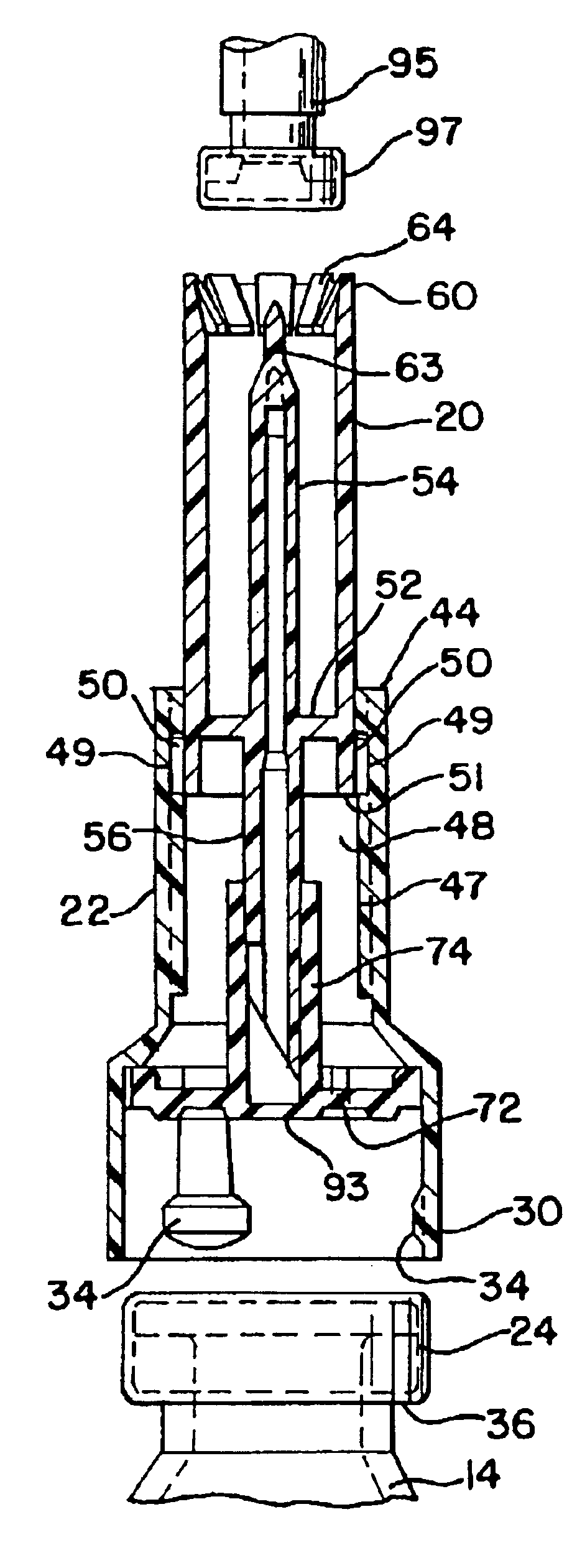
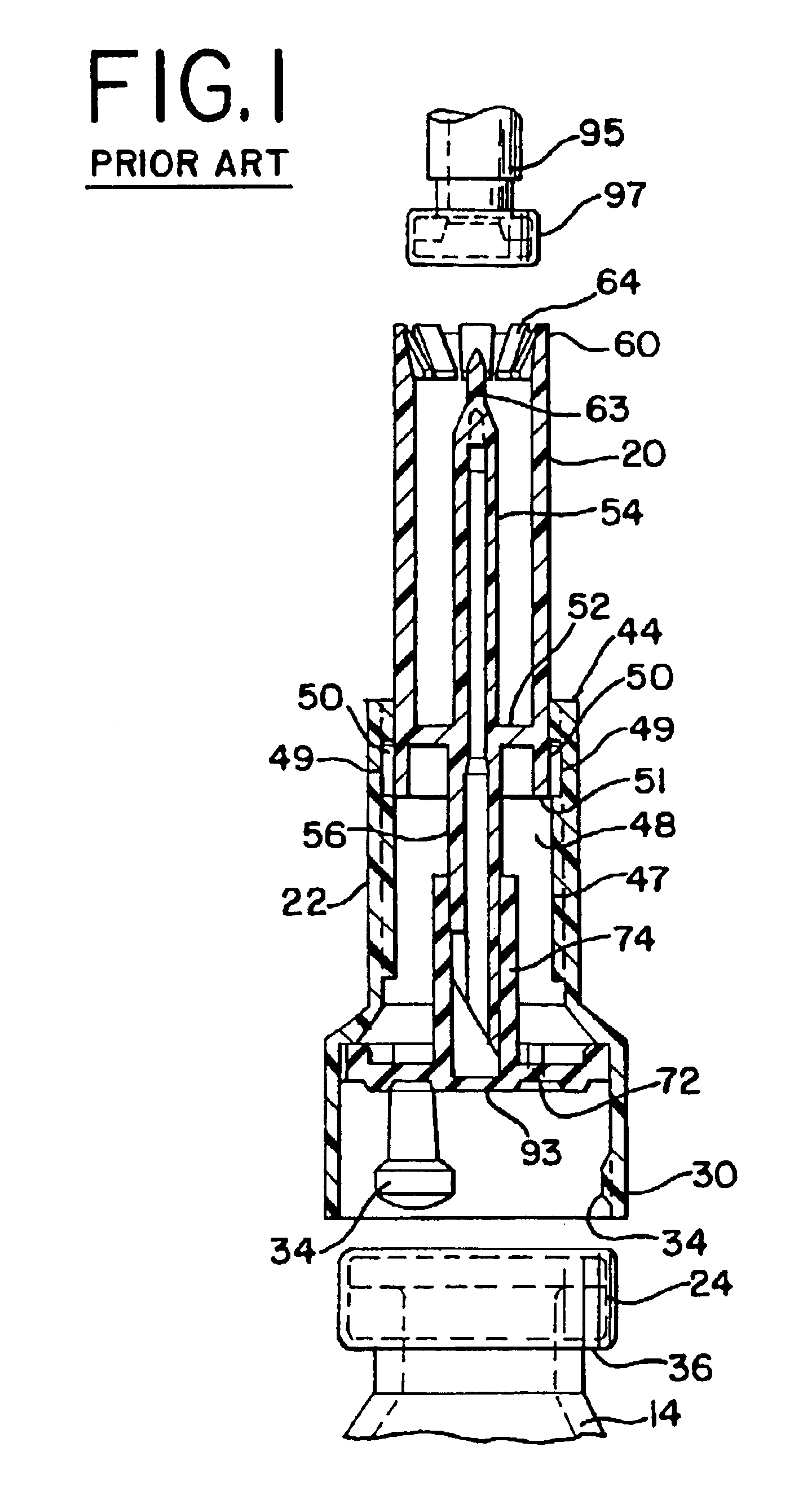
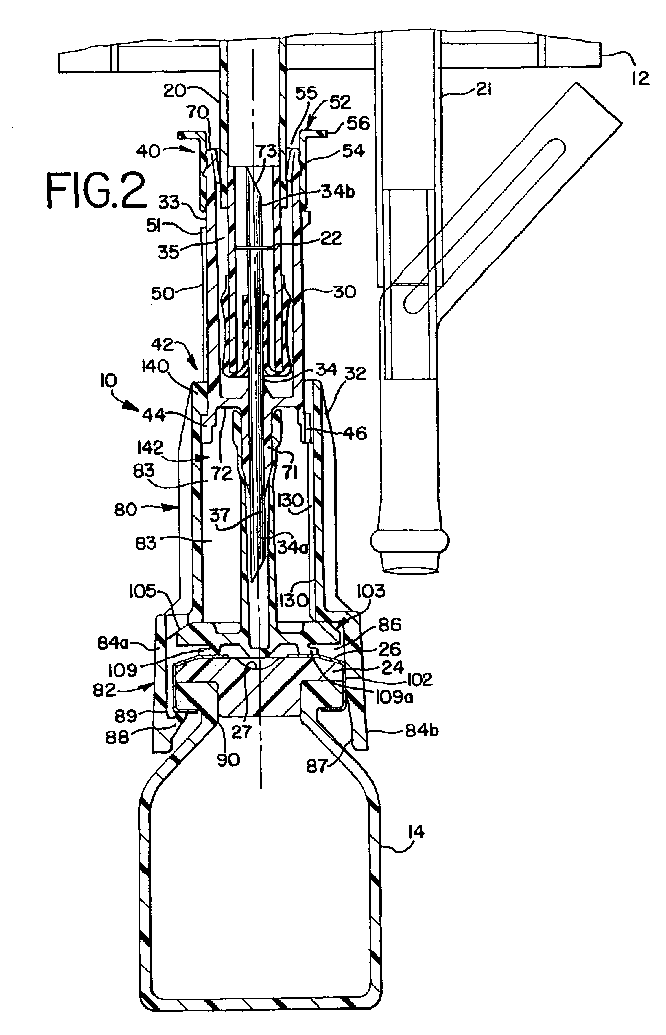
The present invention provides a connector device that is used to mix two substances within separate containers. More particularly, the invention provides a device to reconstitute a drug with a diluent. To accomplish the reconstitution of the drug, the invention provides an improved apparatus for attaching to a first container, commonly a flexible bag, containing a diluent, to a second container, commonly a vial containing a drug to be reconstituted. The connector provides fluid communication between the two containers so that the drug may be reconstituted, and delivered...


PUM


Abstract

The present invention provides a connector device for establishing fluid communication between a first container and a second container. The device has a first sleeve member having a first and a second end, the first sleeve member having at the first end a first attaching member adapted to attach to the first container. The device further has a second sleeve member having a first end and a second end, the second sleeve member being associated with the first sleeve member and movable with respect thereto from an inactivated position to an activated position, the second sleeve member having at the second end a second attaching member adapted to attach the second sleeve member to the second container. First and second piercing members project from one of the first and second sleeve members for providing a fluid flow path from the first container to the second container, and the first and second piercing members are independently hermetically sealed.

Description

TECHNICAL FIELDThe present invention relates generally to the delivery of a beneficial agent to a patient. More specifically, the present invention relates to an improved device for reconstituting a beneficial agent to be delivered to a patient.BACKGROUND OF THE INVENTIONMany drugs are unstable even for a short period of time in a dissolved state and therefore are packaged, stored, and shipped in a powdered or lyophilized state to increase their shelf life. In order for powdered drugs to be given intravenously to a patient, the drugs must first be placed in liquid form. To this end, these drugs are mixed or reconstituted with a diluent before being delivered intravenously to a patient. The diluents may be, for example, a dextrose solution, a saline solution, or even water. Typically the drugs are stored in powdered form in glass vials or ampules.Other drugs, although in a liquid state, must still be diluted before administering to a patient. For example, some chemotherapy drugs are ...

Claims


Application Information

Patent Timeline
Patent Type & Authority Patents(United States)
IPC IPC(8): A61J1/00A61J1/05F02D9/02A61J1/10A61J1/20A61J3/00F02D9/10F02D11/10
CPCA61J1/2089F02D9/1065F02D11/10A61J1/10A61J1/1475A61J1/2096A61J2001/2013Y10S604/905A61J2001/2055A61J2205/20A61J2001/2051A61J1/2055A61J1/2051A61J1/2013A61J1/201Y10T137/87957
Inventor FOWLES, THOMAS A.PROGAR, THOMAS J.WEINBERG, ROBERT J.FULLER, CRAIG A.
Owner BAXTER INT INC
Why Eureka
Try Eureka