Energy-efficient duct, head cell with duct and methods

a head cell and energy-efficient technology, applied in the direction of centrifuges, liquid displacement, separation processes, etc., can solve problems such as wear and tear, and achieve the effects of improving efficiency, reducing the operating energy requirement of the head cell, and improving performance and efficiency

Inactive Publication Date: 2005-02-08
EUTEK SYST
View PDF30 Cites 6 Cited by
  • Summary
  • Abstract
  • Description
  • Claims
  • Application Information

AI Technical Summary

Benefits of technology

New methods and associated apparatus are provided for operating a treatment apparatus, e.g., a head cell, with improved performance and efficiency. Influent is fed downwardly to a head cell, which decreases the head cell operating energy (i.e., head) requirement and increases efficiency. Because the new method requires less head,

Problems solved by technology

The remaining fine grit

Method used


Image

  • Energy-efficient duct, head cell with duct and methods
  • Energy-efficient duct, head cell with duct and methods
  • Energy-efficient duct, head cell with duct and methods

Examples


Embodiment Construction

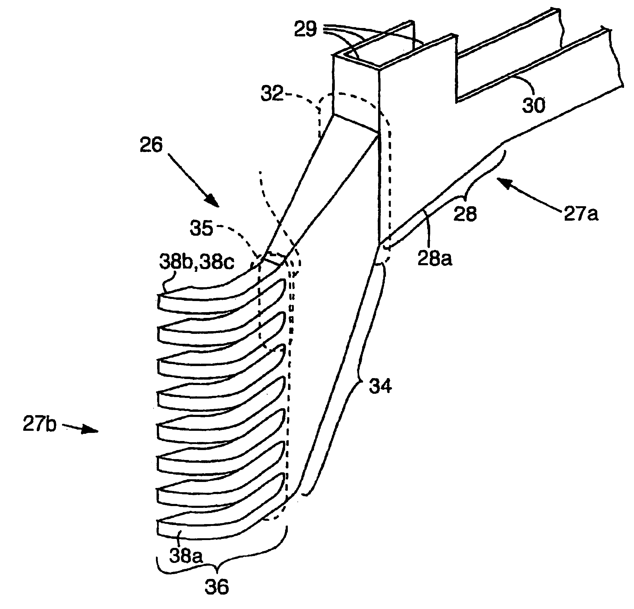
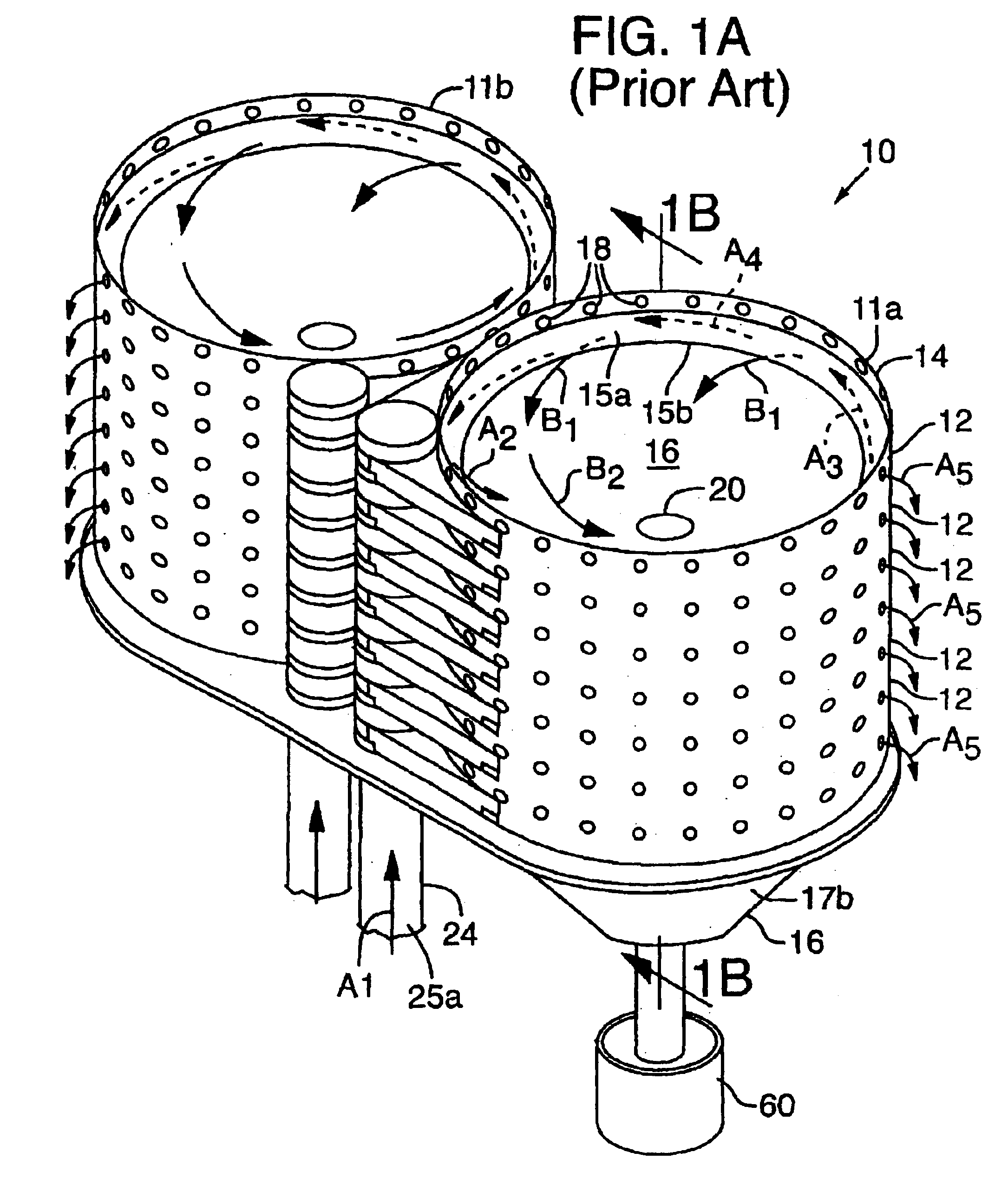
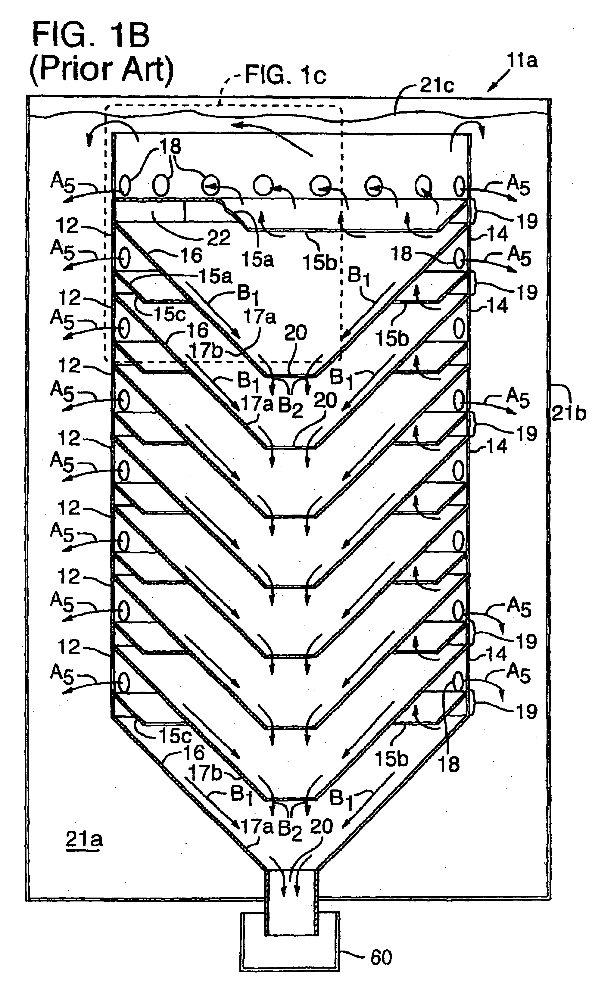
As described below, new methods and apparatus provide for operating a treatment apparatus with improved performance and efficiency. In specific implementations, the wastewater treatment apparatus is a head cell that removes grit from influent at an initial stage before the resulting effluent from the head cell is subjected to subsequent treatment. Efficient grit removal requires achieving particular flow conditions in the head cell, which also implicates the design of the duct leading to the head cell.

Grit and Grit Removal

Removing grit from influent before subsequent treatment can help alleviate two problems: (1) wear (especially of rotating parts), and (2) deposition and accumulation of grit that leads to loss of performance. As used herein, “grit” refers to inorganic, settleable solids that are denser than water (i.e., having a specific gravity greater than 1.0). Grit includes both particles that travel along the bottoms of pipes, channels, ducts, etc., and particles that are susp...


PUM

PropertyMeasurementUnit
Velocityaaaaaaaaaa
Levelaaaaaaaaaa
Velocityaaaaaaaaaa

Abstract

A duct for conveying influent to a head cell having multiple, vertically aligned trays has an inlet end and an outlet end. The inlet end can be connected to an influent channel positioned at a level above the head cell apparatus. The outlet end is positioned downstream of the inlet end and can be connected to the head cell. The outlet end has multiple, discrete nozzles that are spaced apart in a vertical direction and correspond in number to the multiple trays. Influent that enters the inlet end of the duct travels downwardly and exits the duct through orifices in the nozzles, entering each of the respective trays.

Description

BACKGROUNDThe present invention relates to a head cell apparatus used in wastewater treatment, and in particular, to an energy-efficient duct and methods used for conveying wastewater to be treated (i.e., influent) to the head cell.One phase of wastewater treatment is separating “grit,” which is high-density, inorganic, settleable particles, from the influent. Grit causes wear to downstream treatment equipment and, if it accumulates, loss of performance.One type of apparatus used for separating grit from influent is referred to as a head cell. Other approaches to removing grit have involved the use of a horizontal mechanically rotating element (e.g., a paddle or propeller) that circulates the influent within a surrounding cylindrical tank to separate the grit from the influent and cause it to gather in an accumulating well. By way of contrast, head cells separate grit by a continuous hydraulic action and do not require any mechanically-induced motion. Head cells are also self-cleani...

Claims


Application Information

Patent Timeline
IPC IPC(8): B01D21/00C02F1/00
CPCB01D21/0045B01D21/0093B01D21/2411B01D21/245B01D21/26B01D21/2427C02F1/006
Inventor WILSON, GEORGE E.
Owner EUTEK SYST
Why Eureka
Try Eureka