Laser-induced plasma micromachining

a laser ablation and plasma technology, applied in the field of laser ablation, can solve the problems of micromachining, laser micromachining materials typically require high precision and quality, and the formation of craters and heat-affected zones

Inactive Publication Date: 2005-02-08
CATERPILLAR INC
View PDF5 Cites 40 Cited by
  • Summary
  • Abstract
  • Description
  • Claims
  • Application Information

AI Technical Summary

Benefits of technology

In accordance with yet another aspect of the present invention, a method for forming an orifice in a fuel injector nozzle tip is disclosed. The method includes providing the fuel injector nozzle tip in an ambient atmosphere. A plurality of laser pulses are generated, each of the plurality of laser pulses having a pulse width of 1 ps or less and a fluence of 10-500 J/cm2. The plurality of laser pulses are directed to trepan the fuel injector nozzle tip. A gas is provided such that the plurality of laser pulses trepanning the target material interact with the gas to form a plasma. The orifice is then formed by removing a portion of the fuel injector nozzle tip by interaction of the plasma with a surface of the fuel injector nozzle tip.
In ...

Problems solved by technology

Problems arise in micromachining, however, because laser micromachined materials typically require high precision and quality.
As a result, partial re-solidification of the melt zone can occur causing the formation of craters and heat-affected zones.
Other problems include ...

Method used


Image

  • Laser-induced plasma micromachining
  • Laser-induced plasma micromachining
  • Laser-induced plasma micromachining

Examples


Embodiment Construction

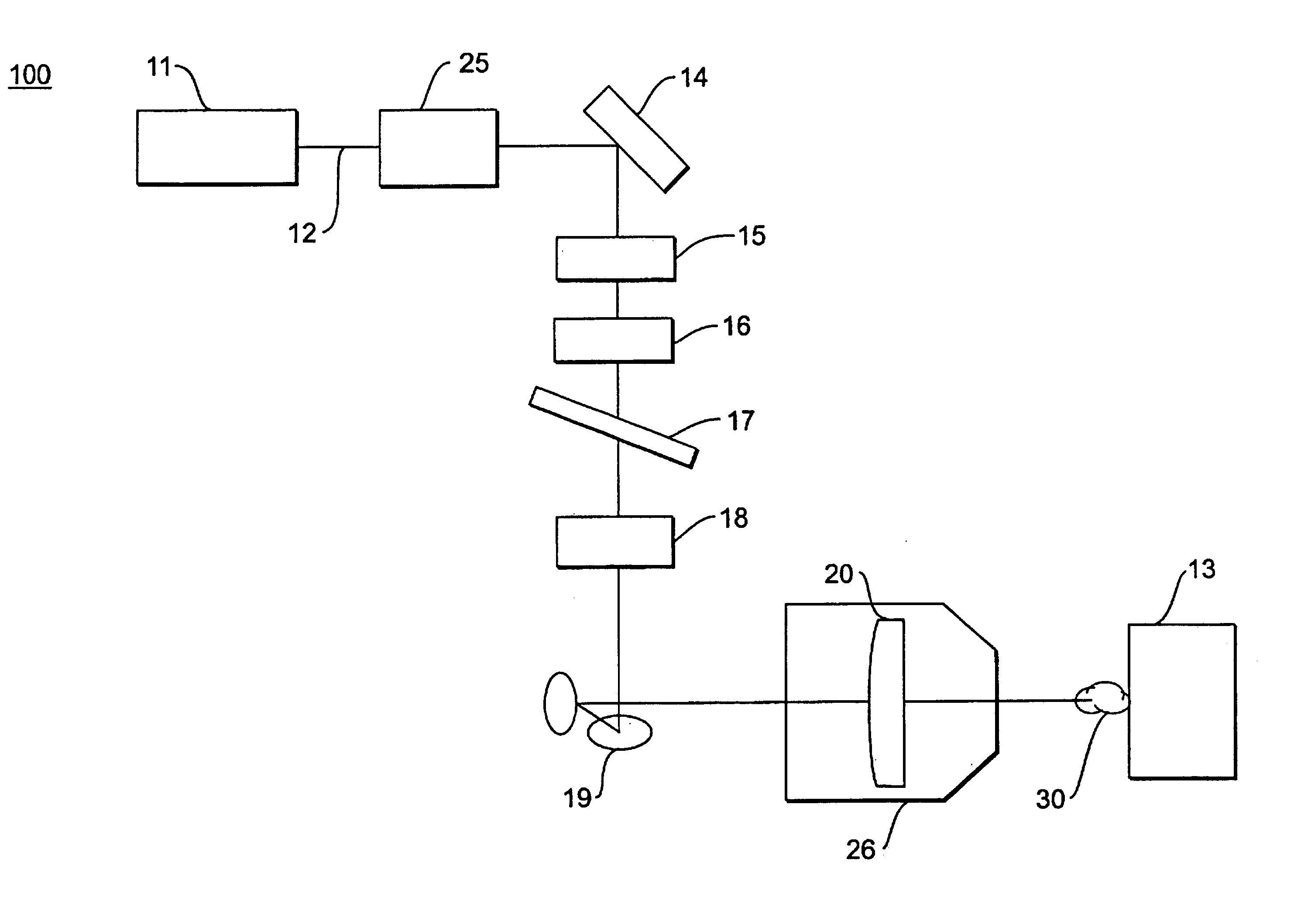
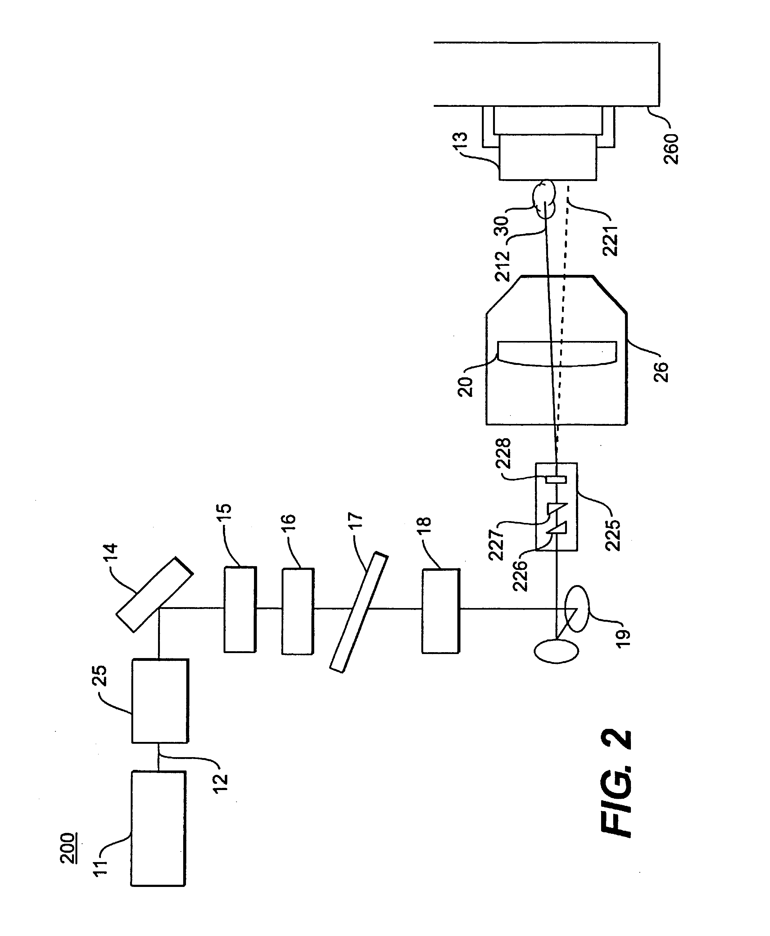
FIG. 1 depicts an exemplary system 100 for laser ablation. A laser system 11 can be any chirped pulse amplified laser system capable of generating pulses having pulse widths of 1 picosecond (ps) or less, such as, for example, femtosecond or picosecond laser systems using a Ti:Sapphire oscillator. Other examples of chirped pulse amplified laser systems include those using Nd:Glass, Yb:Glass, or hybrid oscillators. The generated pulses are directed along a path 12 towards a target material 13 by various optical components. The optical components along optical path 12 may include, for example, a mirror 14, a shutter 15, a ½ wave plate 16, a beam splitter 17, a ¼ wave plate 18, periscope mirrors 19, and a lens 20. A single shot autocorrelator 25 positioned in path 12 may also optionally be used to measure the pulse width. One of skill in the art will recognize that the optical system depicted in FIG. 1 is exemplary and that other configurations and optical components can be used without...


PUM

PropertyMeasurementUnit
Timeaaaaaaaaaa
Timeaaaaaaaaaa
Diameteraaaaaaaaaa

Abstract

A method and system for laser ablating a target material in an ambient atmosphere are disclosed. The method includes generating one or more laser pulses, each of the laser pulses having a pulse width of 1 picosecond (ps) or less and a pulse energy of 50 micro joules (μJ) or more. The laser pulses are directed towards the target material such that the laser pulses interact with a gas to form a plasma. The plasma removes a portion of the target material by interaction of the plasma with the target material.

Description

TECHNICAL FIELDThe present invention relates to laser ablation and, more particularly, to apparatus and processes for micromachining by laser ablation.BACKGROUNDLasers are used in a variety of machining applications. In particular, continuous wave (CW) and long pulse width lasers have been used to cut, drill, surface modify, and mark target materials. Energy from an impinging laser beam or pulse typically beats a target material from a solid phase through a liquid phase to a vapor phase causing expansion and expulsion of target material.Problems arise in micromachining, however, because laser micromachined materials typically require high precision and quality. For CW and long pulse width lasers, the distance over which the heat from the laser pulse is dispersed is greater than the absorption length of the laser. As a result, partial re-solidification of the melt zone can occur causing the formation of craters and heat-affected zones. Other problems include surface contamination and...

Claims


Application Information

Patent Timeline
IPC IPC(8): B23K26/36B23K26/12B23K26/00B23K26/38B23K26/18C23F4/00F02M61/00F02M61/16
CPCB23K26/0639B23K26/0648B23K26/0665B23K26/123F02M61/168B23K26/365B23K26/386C23F4/00B23K26/18B23K26/064B23K26/361B23K26/389
Inventor GROEN, CALE E.KOCH, JUSTIN LEEWHITE, WILLIAM E.
Owner CATERPILLAR INC
Why Eureka
Try Eureka