Continuous structural wall system

a continuous structural and wall technology, applied in the direction of walls, building components, constructions, etc., can solve the problems of unsupported and unguided wiring through the sheeted panel, requiring skilled laborers, sophisticated equipment and considerable time to assemble and erect a structure, and using any of the aforementioned conventional techniques

Inactive Publication Date: 2005-02-15
STARKE CHARLES
View PDF40 Cites 62 Cited by
  • Summary
  • Abstract
  • Description
  • Claims
  • Application Information

AI Technical Summary

Benefits of technology

A composite panel incorporates a horizontally extending hollow load bearing header having hollow studs spaced at intervals throughout the width of the panel. The hollow header and hollow studs form horizontal and vertical chases for accommodating utilities such as wiring, cabling and conduit. Holes are formed in the horizontal chase coincident with the vertical chases to permit communication therebetween. The utilities are protected from damage as a result of penetration by mechanical fasteners used to assemble the panels into wall structures. Protective barrier members are positioned within the hollow chases, leaving a core open for the passage of the utilities. Further, the header provides structural rigidity and enables one to provide door and window penetrations substantially anywhere in the wall.

Problems solved by technology

Using any of the aforementioned conventional techniques requires skilled laborers, sophisticated equipment and considerable time to assemble and erect a structure.
If wiring is not installed prior to installation, subsequent fishing of wiring through the sheeted panel is unsupported and unguided either horizontally through notches between the furring strips or vertically in the spaces created between the furring strips.
The use of adhesively assembled wall panels has not yet been approved under many building codes.
In Canada, Canada Mortgage and Housing Corporation (CMHC) negatively views the use of any laminates or adhesive bonding that are exposed to the environment.
Specifically, known disadvantages of adhesive bonding include de-lamination of the bond when exposed to the elements.
It is uncertain how long the bond will hold and thus CMHC believes that it is risky to use where structural integrity is required for an extended time.
Open channels at the top and bottom of the wall panel are utilized for affixing the panel to the floor and to the roof and as such are compromised by fasteners extending through the channels making them incompatible with standard electrical wiring.
Armor jacketed cable that is impervious to fasteners is required, which adds to the overall expense and man hours required.
While providing load carrying support above openings formed in the panel, the header does not provide a passage for electrical services and the like.

Method used


Image

  • Continuous structural wall system
  • Continuous structural wall system
  • Continuous structural wall system

Examples


Embodiment Construction

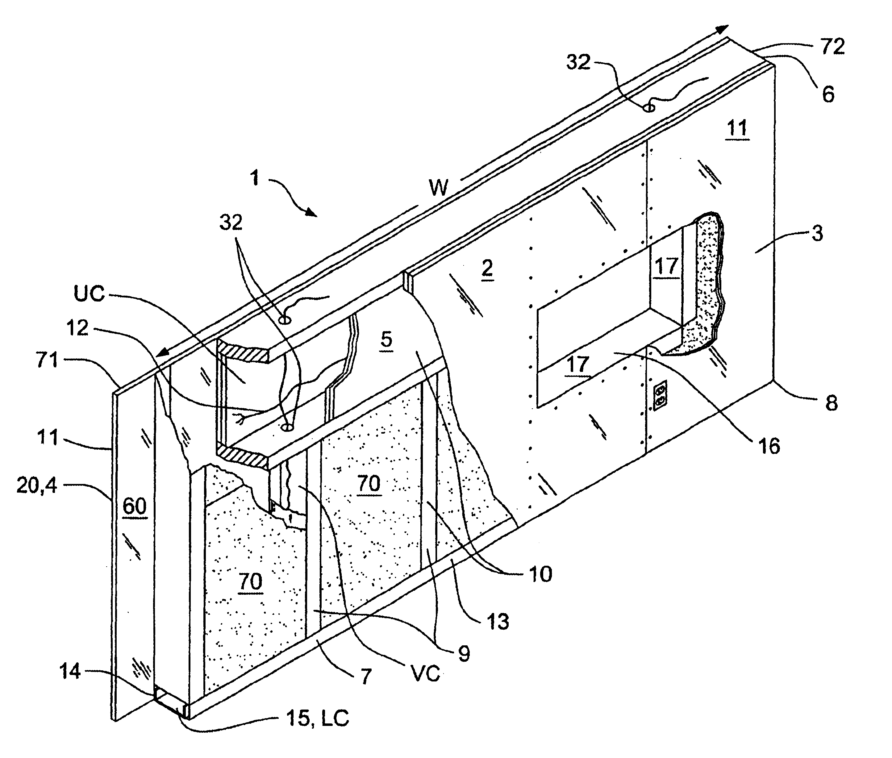
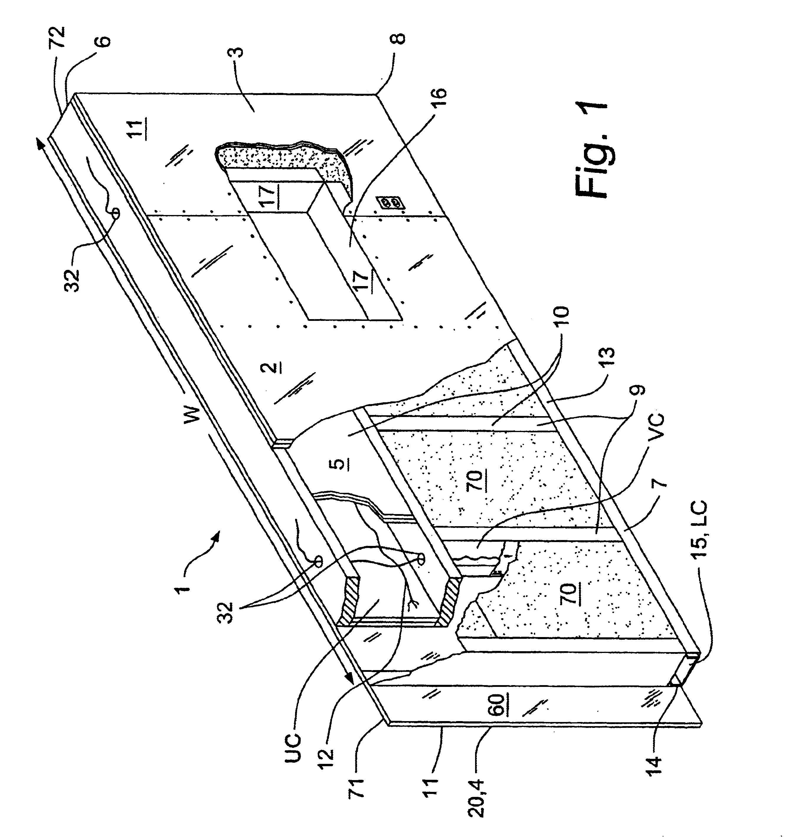
As shown in FIGS. 1-3, a composite wall panel 1 is used to form at least a portion of a substantially rectangular structural wall 2 having opposing planar surfaces 3, 4, one of which may be exposed to the environment. The panel 1 comprises a hollow header 5 formed horizontally across a top 6 of the panel 1 and a base 7 formed horizontally across a bottom 8 of the panel 1 for attaching to an existing floor structure (not shown). The hollow header 5 is spaced from the base 6 by a plurality of hollow studs 9 positioned at intervals intermediate a width “w” of the panel, forming a frame 10. Sheeting material 11 is affixed to the frame 10 on the opposing planer surfaces 3,4 for forming the panel 1. Once sheeted, the panel 1 has limited access therein for the installation of utilities 12 such as wire, cabling and conduit. The hollow header 5 and studs 9 form vertical chases “VC” and an upper horizontal chase “UC” which can communicate with each other so as to enable ready installation of ...


PUM


Abstract

A composite wall panel having continuous upper and lower hollow horizontal chases and spaced hollow vertical chases formed throughout the panel to permit passage of electrical wiring and the like. The chases have protective barriers to protect the wiring from penetration and damage due to mechanical fasteners used to manufacture the panel and to construct load bearing walls using a plurality of manufactured panels. Further, the panel has a continuous header to provide structural rigidity and to permit rapid manufacturing of the panel without the need to frame openings, such as doors and windows, at the time of manufacture. Openings are cut in the panels and finished after the walls are constructed.

Description

FIELD OF THE INVENTIONThe present invention relates to composite wall systems for modular construction. More particularly the invention relates to formation of chases for services, vertically and horizontally, within the structural elements of the wall system.BACKGROUND OF THE INVENTIONConventional wisdom in construction techniques has been to remain with tried, tested and true materials and methodologies. Accordingly, conventional wall frame construction continues to utilize either 2″×4″ or 2″×6″ construction in either a stick framing or a unit framing technique. Additionally, stressed-skin panels have been introduced in which two sheets of building material are sandwiched together about a foam core to provide insulation.In stick frame construction, a wall is generally built in place, using a framework of repeating, evenly spaced wall studs. At openings, such as windows and doors, a custom framework is constructed, including a lintel over the opening, to ensure structural integrity...

Claims


Application Information

Patent Timeline
Patent Type & Authority Patents(United States)
IPC IPC(8): E04C2/52E04C2/38
CPCE04C2/521E04C2/384E04C2/00E04C2/52
Inventor STARKE, CHARLES
Owner STARKE CHARLES
Why Eureka
Try Eureka