Conveyorized storage and transportation system

a technology of conveying storage and transportation system, which is applied in the direction of charge manipulation, furniture, instruments, etc., can solve the problems of not being able to execute parallel workpiece manipulations by stocker robots, unable to accept the conveying method of transportation in these industries, and unable to achieve single workpiece manipulation limitations, etc., to achieve convenient configuration

Inactive Publication Date: 2005-02-15
MIDDLESEX GEN INDS MESNE
View PDF15 Cites 87 Cited by
  • Summary
  • Abstract
  • Description
  • Claims
  • Application Information

AI Technical Summary

Benefits of technology

The presently disclosed system includes an easily configurable storage system which is particularly well-suited for use with clean-environment conveyors, such as those described in U.S. Pat. No. 6,047,812 to Horn et al, incorporated herein by reference. The storage system includes modular conveyor elements which may be provided parallel to and adjacent a ceiling mounted conveyor network. The conveyor elements may be provided as “oneway” paths which, when provided with plural transfer elements with respect to the path of the conveyor elements, can enable the circulation of a work-piece or a carrier of work-pieces from a storage matrix to a transfer path and back to the storage matrix. This avoids a problem with a needed work-piece being located in the middle of other not-needed work-pieces in the storage matrix.

Problems solved by technology

Historically, a conveyor methodology of transport has not been accepted in these industries, where ultra-clean handling of material is required.
As is evident, no parallel work-piece manipulations can be executed by the stocker robot while this storing activity is underway.
The same limitation to single work-piece manipulation exists when the stocker robot is in the process of retrieving a work-piece.
Another deficiency associated with stockers pertains to the amount of floor space which such systems typically occupy.
If multiple stockers are provided as a means for lessening the bottleneck in work-piece flow as compared to the use of a single stocker, that much more floor space is consumed.
The cost of the overall system is significantly raised as a consequence.

Method used


Image

  • Conveyorized storage and transportation system
  • Conveyorized storage and transportation system
  • Conveyorized storage and transportation system

Examples


Embodiment Construction

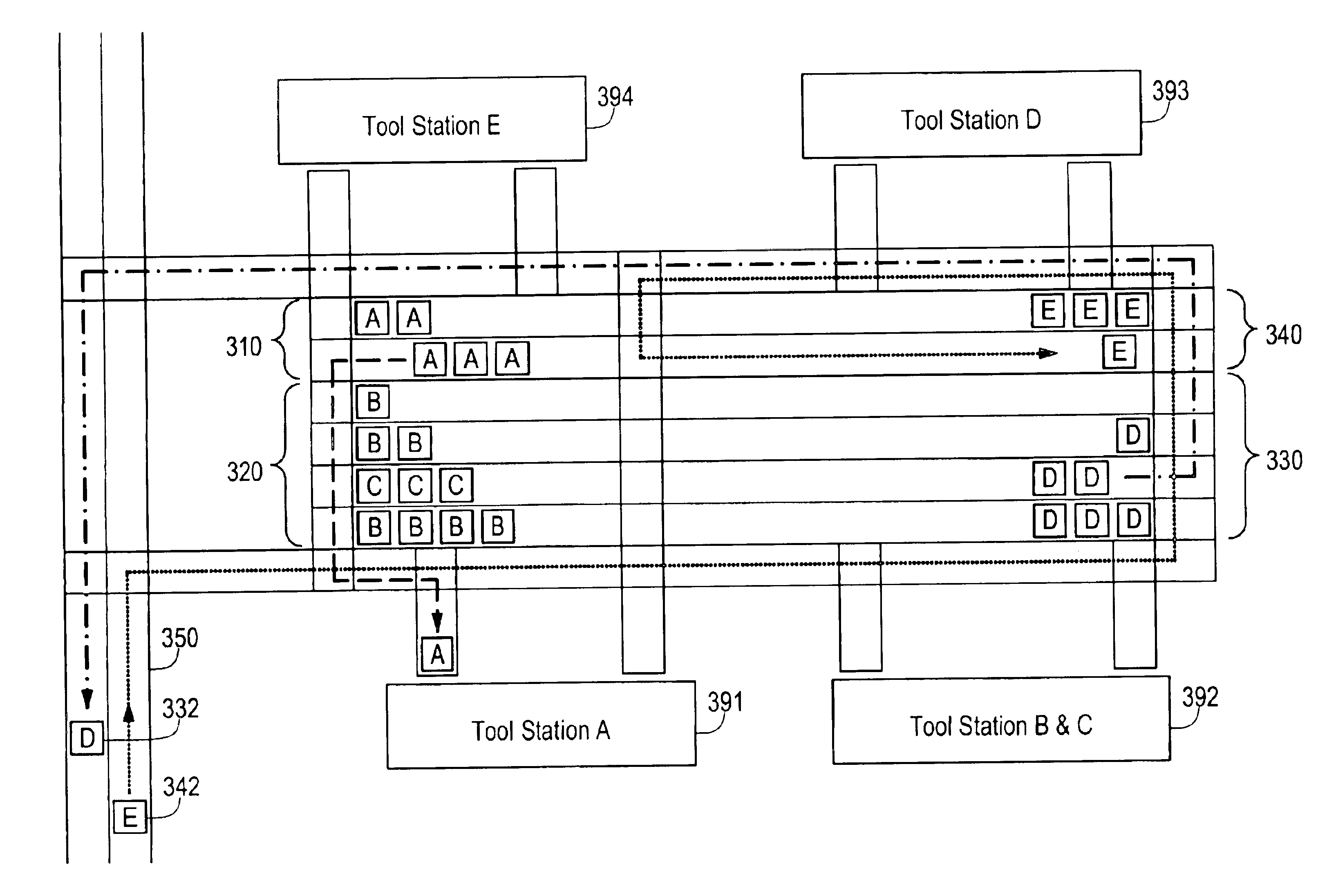
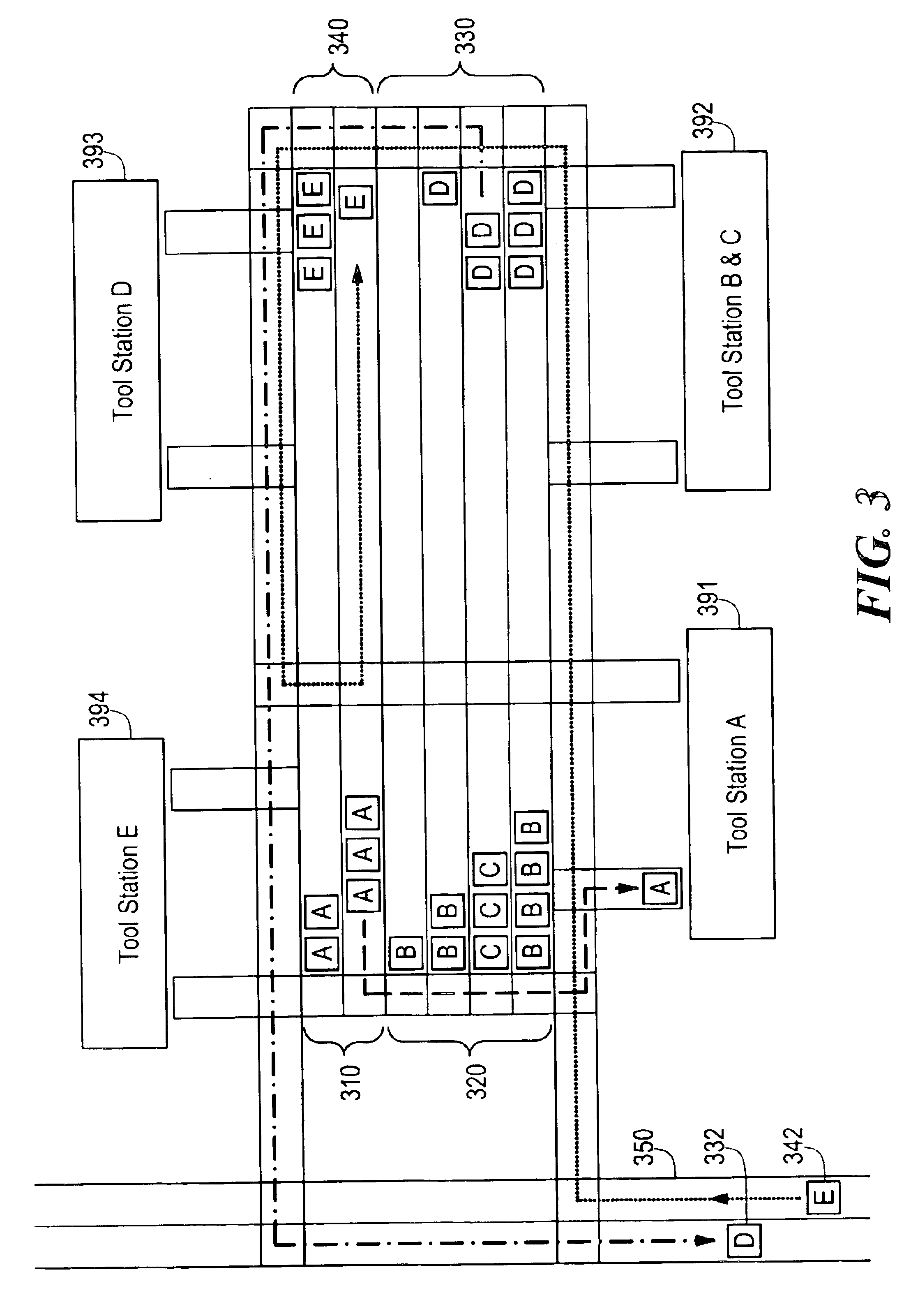
The conveyorized storage and transport system according to the embodiments of the present invention may be used in any type of processing industry requiring storage for maintaining inventories at multiple processing stations. The manufacture of semiconductor devices is one example of an industry that is particularly suited for the features provided by the storage and transport system according to the embodiments of the present invention. In the illustrations, various embodiments of the presently disclosed storage and transport system are referred to as a “field stocker.”

Carriers conveyed by a clean-environment conveyor system may be pallets carrying one or more individual work-pieces. Alternatively, the conveyor elements may transport the work-pieces themselves without the need for carriers. In a semiconductor manufacturing process, substrates are usually carried in a transport carrier, while in flat panel manufacturing, the work-pieces may ride in carriers or directly on the convey...


PUM


Abstract

A configurable storage system particularly suited for use with clean environment conveyors is disclosed. The storage system includes modular conveyor track elements which may be provided as one way paths which, when provided with plural transfer elements with respect to a conveyor highway, enable the rotation of a workpiece from a storage matrix to a transfer path and back to the storage matrix.

Description

STATEMENT REGARDING FEDERALLY SPONSORED RESEARCH OR DEVELOPMENTN / ABACKGROUND OF THE INVENTIONIn clean-environment manufacturing industries, such as the manufacturing of flat panel display devices and semiconductors, there is a need to handle large amounts of in-process inventories. In these industries, discrete vehicle-type transports, such as monorail vehicles or automated guided vehicles, have prevailed, especially in the front-end of clean manufacturing processes. Manually operated vehicle-type carts have served such industries as well.Historically, a conveyor methodology of transport has not been accepted in these industries, where ultra-clean handling of material is required. Recent advances in conveyor technology have made conveyor systems more attractive for use in clean-environment manufacturing industries. Some of these advances include: improved cassettes for riding directly on the conveyor and limiting the bounce in wafers carried thereon; standardized runners for accepti...

Claims


Application Information

Patent Timeline
Patent Type & Authority Patents(United States)
IPC IPC(8): B65G49/06B65G49/05H01L21/00H01L21/677H01L21/67
CPCB65G49/064B65G49/068H01L21/67727H01L21/67276B65G2249/02
Inventor HORN, GEORGE
Owner MIDDLESEX GEN INDS MESNE
Why Eureka
Try Eureka