Airfoil shape for a turbine bucket

a technology of turbine bucket and airfoil, which is applied in the direction of reaction engines, engine manufacturing, chemical processes, etc., can solve the problems of significant extension of the part life, reduce thermal and mechanical stresses, minimize or eliminate cracking problems, and improve the performance of gas turbines

Inactive Publication Date: 2005-02-15
GENERAL ELECTRIC CO
View PDF16 Cites 155 Cited by
  • Summary
  • Abstract
  • Description
  • Claims
  • Application Information

AI Technical Summary

Benefits of technology

In accordance with the preferred embodiment of the present invention there is provided a unique airfoil shape for a bucket of a gas turbine, preferably the first stage bucket, that enhances the performance of the gas turbine and which resolves the cracking problem. It is believed that the cause of the cracking is attributable to low cycle fatigue introduced by mechanical and thermal loads in the vicinity of the root cooling hole. A reduction of thermal and mechanical stresses at the root cooling hole of the trailing edge minimizes or eliminates the cracking problem and results in a significant extension of the part life. The airfoil shape hereof also improves the interaction between various stages of the turbine and affords improved aerodynamic efficiency while simultaneously reducing first stage airfoil thermal and mechanical stresses.

Problems solved by technology

It is believed that the cause of the cracking is attributable to low cycle fatigue introduced by mechanical and thermal loads in the vicinity of the root cooling hole.
A reduction of thermal and mechanical stresses at the root cooling hole of the trailing edge minimizes or eliminates the cracking problem and results in a significant extension of the part life.

Method used


Image

  • Airfoil shape for a turbine bucket
  • Airfoil shape for a turbine bucket
  • Airfoil shape for a turbine bucket

Examples


Embodiment Construction

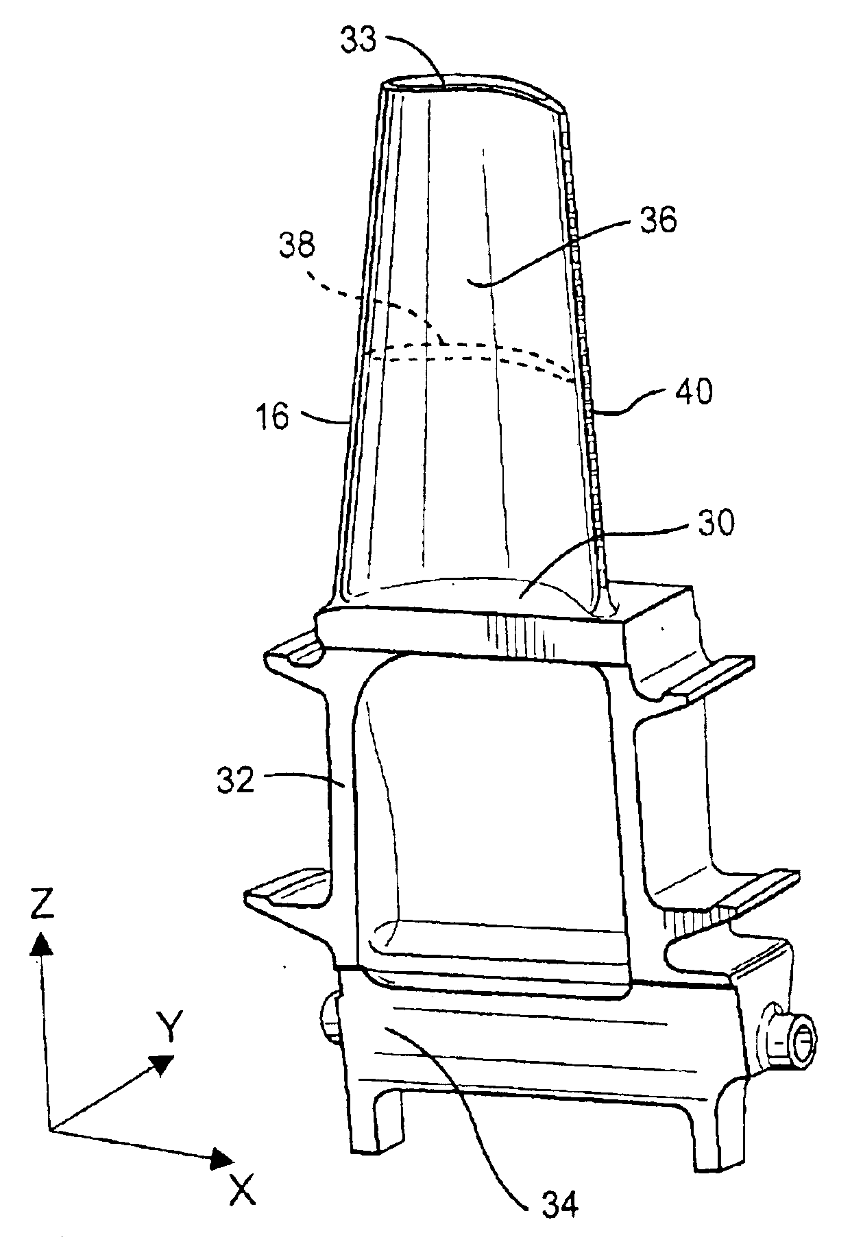
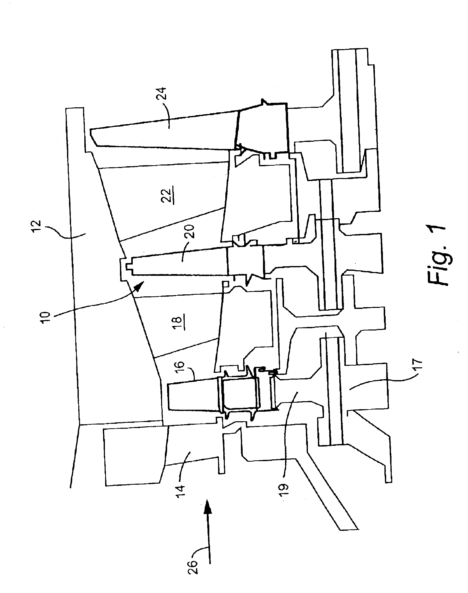
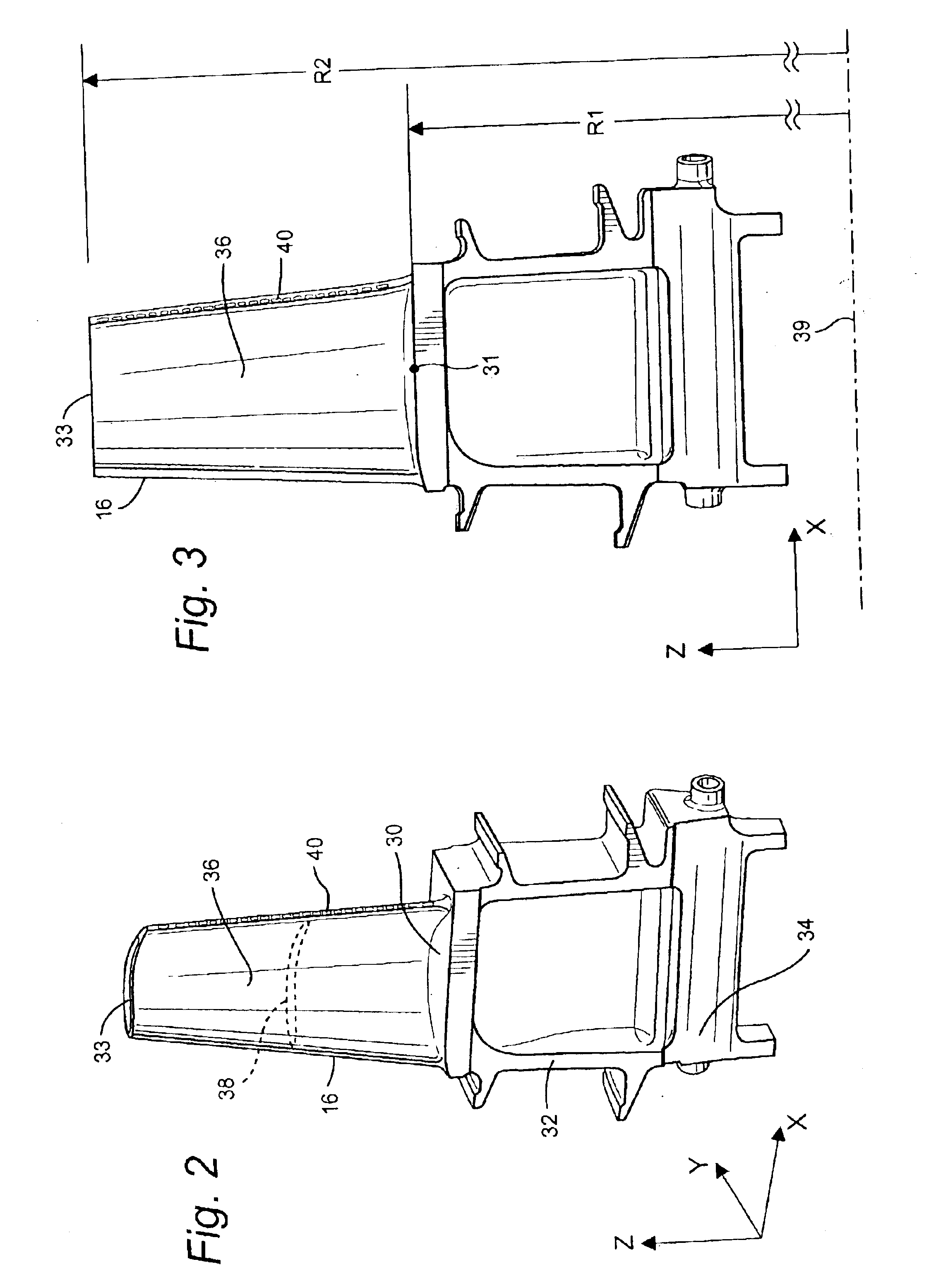
Referring now to the drawings, particularly to FIG. 1, there is illustrated a hot gas path, generally designated 10, of a gas turbine 12 including a plurality of turbine stages. Three stages are illustrated. For example, the first stage comprises a plurality of circumferentially spaced nozzles14 and buckets 16. The nozzles are circumferentially spaced one from the other and fixed about the axis of the rotor. The first stage buckets 16, of course, are mounted on the turbine rotor 17. A second stage of the turbine 12 is also illustrated, including a plurality of circumferentially spaced nozzles 18 and a plurality of circumferentially spaced buckets 20 mounted on the rotor 17. The third stage is also illustrated including a plurality of circumferentially spaced nozzles 22 and buckets 24 mounted on rotor 17. It will be appreciated that the nozzles and buckets lie in the hot gas path 10 of the turbine, the direction of flow of the hot gas through the hot gas path 10 being indicated by th...


PUM


Abstract

First stage turbine buckets have airfoil profiles substantially in accordance with Cartesian coordinate values of X, Y and Z set forth Table I wherein X and Y values are in inches and the Z values are non-dimensional values from 0 to 1 convertible to Z distances in inches by multiplying the Z values by the height of the airfoil in inches. The X and Y values are distances which, when connected by smooth continuing arcs, define airfoil profile sections at each distance Z. The profile sections at each distance Z are joined smoothly to one another to form a complete airfoil shape. The X, Y and Z distances may be scalable as a function of the same constant or number to provide a scaled up or scaled down airfoil section for the bucket. The nominal airfoil given by the X, Y and Z distances lies within an envelop of ±0.055 inches in directions normal to the surface of the airfoil.

Description

BACKGROUND OF THE INVENTIONThe present invention relates to an airfoil for a bucket of a stage of a gas turbine and particularly relates to a first stage turbine bucket airfoil profile.Many system requirements must be met for each stage of the hot gas path section of a gas turbine in order to meet design goals including overall improved efficiency and airfoil loading. Particularly, the buckets of the first stage of the turbine section must meet the thermal and mechanical operating requirements for that particular stage. A particular problem associated with air-cooled bucket airfoils is a systematic cracking at the root cooling hole of the trailing edge of the first stage bucket. The cracking problem degrades bucket life.BRIEF DESCRIPTION OF THE INVENTIONIn accordance with the preferred embodiment of the present invention there is provided a unique airfoil shape for a bucket of a gas turbine, preferably the first stage bucket, that enhances the performance of the gas turbine and whic...

Claims


Application Information

Patent Timeline
Patent Type & Authority Patents(United States)
IPC IPC(8): F01D5/14F01D5/18F01D5/02F01D5/06
CPCF01D5/141F05D2250/74Y10S416/02F05D2220/3212F05D2240/301F01D5/18
Inventor ZHANG, XIUZHANG JAMESCHIURATO, ANTHONY AARONBLACK, RACHEL KYANOPESETSKY, DAVID SAMUEL
Owner GENERAL ELECTRIC CO
Why Eureka
Try Eureka