Method and devices for peening and cleaning metal surfaces

Inactive Publication Date: 2005-02-15
JAPAN SCI & TECH CORP
View PDF10 Cites 31 Cited by
  • Summary
  • Abstract
  • Description
  • Claims
  • Application Information

AI Technical Summary

Benefits of technology

The inventor of the disclosure specified herein has therefore proceeded with studies on the collapsing impact force of the cavitation bubble and on the cavitating jet's surface modification phenomenon. As a result, it has been verified that the collapsing impact force of the cavitation bubble and the cavitating jet's surface modification effect for example, improving residual stresses, hardening the workpiece and enhancing fatigue strength, are dependen

Problems solved by technology

On such an assumption, an expensive high-pressure pump is employed to increase the pump discharge pressure.
However, satisfactory treatment capability has remained unattainable from the viewpoint of surface treatment.
Fur

Method used


Image

  • Method and devices for peening and cleaning metal surfaces
  • Method and devices for peening and cleaning metal surfaces
  • Method and devices for peening and cleaning metal surfaces

Examples


first embodiment

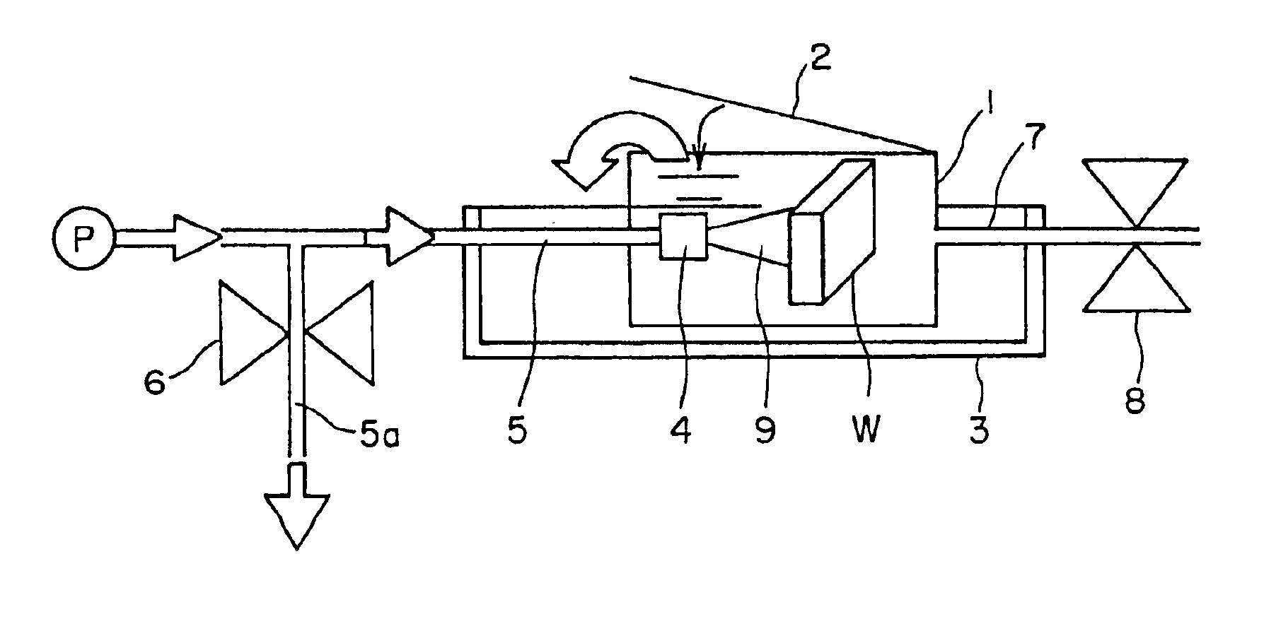
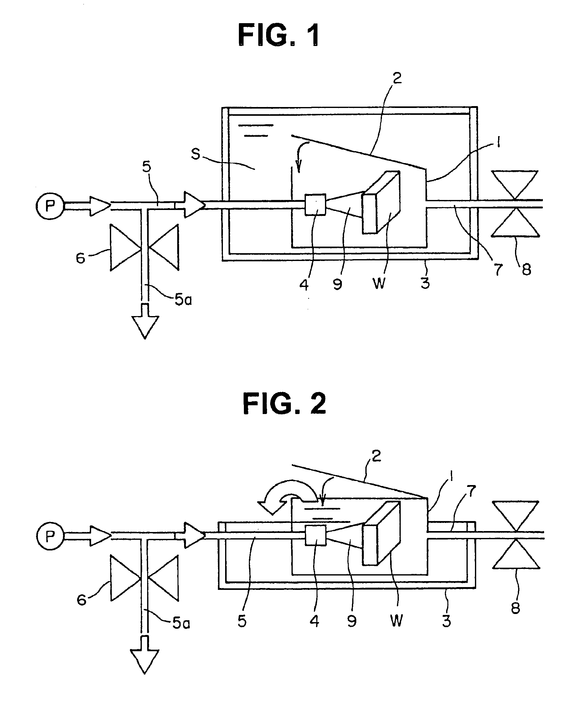
FIG. 1 is a block diagram of the metal part and other surface modification device involved in the

In FIG. 1, is first vessel 1, which permits a workpiece to be delivered and placed with ease, is configured to be hermetically sealable by means of lid 2, to reform the surface of the workpiece.

A second vessel 3 is capable of accommodating identical first vessel 1, and has a depth larger than the height of first vessel 1 so that it can form appropriate space S in the periphery of the first vessel 1.

Nozzle 4 injects a cavitation jet into first vessel 1.

Conduit 5 supplies the nozzle with a high-pressure fluid from first vessel 1.

Control valve 6 regulates the high-pressure fluid flow rate.

Conduit 7 is a conduit through which the fluid is drained from first vessel 1.

Pressure control valve 8 is located in the said conduct to regulate the pressure in the first vessel 1.

The first vessel 1 may be provided with two or more nozzles. It is preferable, moreover, that flow control valve 6 is located ...

second embodiment

Subsequently, the present invention will be described, based on the figures.

FIG. 2 is a block diagram of the metal part and other surface modification device involved in the second embodiment.

The device in the second embodiment has a shallower second vessel 3 than that in the first embodiment. And the second embodiment is configured so that the fluid will overflow at the upper edge of first vessel 1 while allowing the treatment to be performed just like the first embodiment.

In the second embodiment, it is necessary to pressurize first vessel 1 in the interior. Similarly to the first embodiment, therefore, the second embodiment should have lid 2 closed so that the fluid may overflow through the clearance of lid 2. If a weight is placed on lid 1 of first vessel 1, or a spring with a specified spring constant is used to couple the lid with the vessel, a resistance can be applied to the opening of the lid to mechanically pressurize first vessel 1. This applied pressure is controllable u...

embodiment 4

referred to above has the action described below.

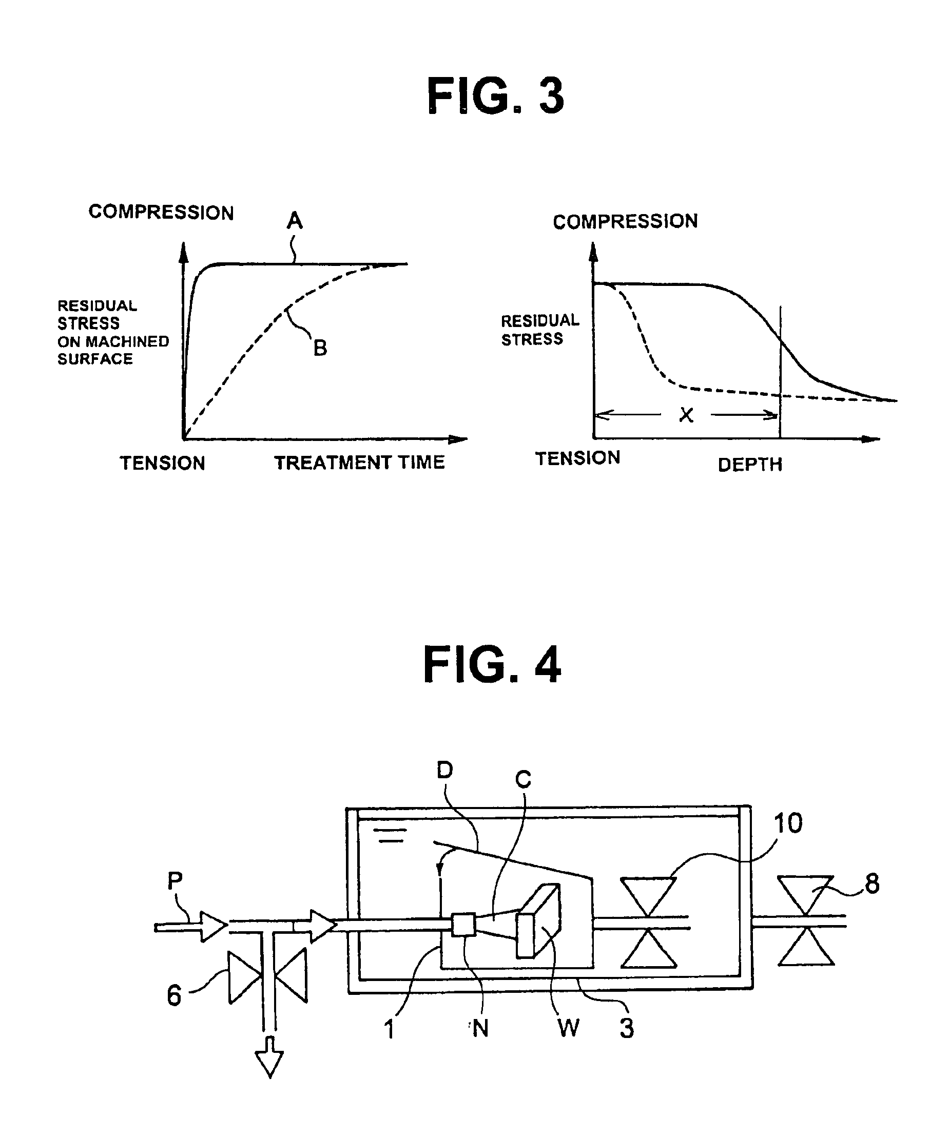
Workpiece 22 is arranged in the fluid in the second vessel 29 and first vessel 21 is placed onto the surface of workpiece 22. Under this condition, a pressurizing fluid is introduced into first vessel 21 and cavitating jet 28 is injected from nozzle 24 into 21 or second vessel 31 to generate cavitation around the jet so that cavitation bubbles will strike workpiece 22. In this stage, the fluid pressure in first vessel21 and the pressure in cavitating jet 28 are controlled, respectively, with pressure control valve 27 and with flow control valve 25. The collapsing impact force of the cavitation bubbles act on the surfaces of the workpiece to bring about a hardening effect on the workpiece surface, an improvement of residual stresses and an enhancement of fatigue strength. The used fluid is discharged to the exterior through gaps between first vessel 21 and the workpiece.

In this embodiment, cavitating jet 28 is generated in the pressuri...


PUM

PropertyMeasurementUnit
Temperatureaaaaaaaaaa
Forceaaaaaaaaaa
Flow rateaaaaaaaaaa

Abstract

This invention relates to a metal part and other surface modification method suitable for the machining industry in which shot peening is typically used to refine the surface of a metal part (to introduce compressive residual stresses, to enhance fatigue strength, to harden the workpiece) and for fields in which parts need be cleaned. According to the present invention, workpiece W is placed within a first vessel which is filled with a fluid. The first vessel is pressurized by controlling the flow rate of the fluid flowing in the first vessel from nozzle 4 distant from said workpiece on the surface and of the fluid flowing from first vessel. Thus, the collapsing impact force of cavitation bubbles is increased so that the machined part will have its surface strengthened and cleaned by applying a peening effect to the surface of the part with said impact force.

Description

FIELD OF ARTThis invention relates to a method of peening metal part surfaces, such as gears, springs, and molds, and to a device in which the method is implemented. More specifically, it relates to a metal part surface modification and cleaning method and the device using this method which is especially suitable for the machining industry where shot peening is typically used to improve metal part surfaces, for example, to form compressive residual, or surface stresses, enhance fatigue strength, harden the workpiece and for use where parts need to be cleaned.BACKGROUND OF THE ARTConventionally, shot peening has been used to improve various metal part surfaces by forming, by example, compressive residual stresses, enhance fatigue strength, harden the workpiece.More recently, to impede stress corrosion cracking and protect materials in critical applications, such as a nuclear reactor vessel, against such cracking, there is also a technique available to suppress the residual stresses o...

Claims


Application Information

Patent Timeline
IPC IPC(8): B24C1/10C21D7/00C21D7/06C21D7/04B23P17/00
CPCB24C1/10C21D7/06C21D7/04
Inventor SOYAMA, HITOSHI
Owner JAPAN SCI & TECH CORP
Why Eureka
Try Eureka