Piston ring

a technology of piston rings and rings, applied in the field of piston rings, can solve the problems of insufficient performance and adverse effect on scuffing resistance, and achieve the effects of excellent scuffing resistance, wear resistance and peeling resistan

Active Publication Date: 2015-10-29
RIKEN CO LTD
View PDF1 Cites 12 Cited by
  • Summary
  • Abstract
  • Description
  • Claims
  • Application Information

AI Technical Summary

Benefits of technology

[0014]An object of the present invention is to provide a piston ring having a hard laminate coating formed by ion plating for excellent scuffing resistance, wear resistance and peeling resistance, which can be used in an environment under high mechanical and thermal load in engines.

Problems solved by technology

Even piston rings having hard chromium nitride (CrN) coatings formed by ion plating, which are now considered as having best scuffing resistance and wear resistance, may fail to exhibit sufficient performance due to the peeling of coatings by cracking and chipping.
Though the metal layers relax stress more than the composite nitride layers of Patent Reference 2, they have an adverse effect on scuffing resistance.

Method used


Image

  • Piston ring
  • Piston ring
  • Piston ring

Examples


example 1

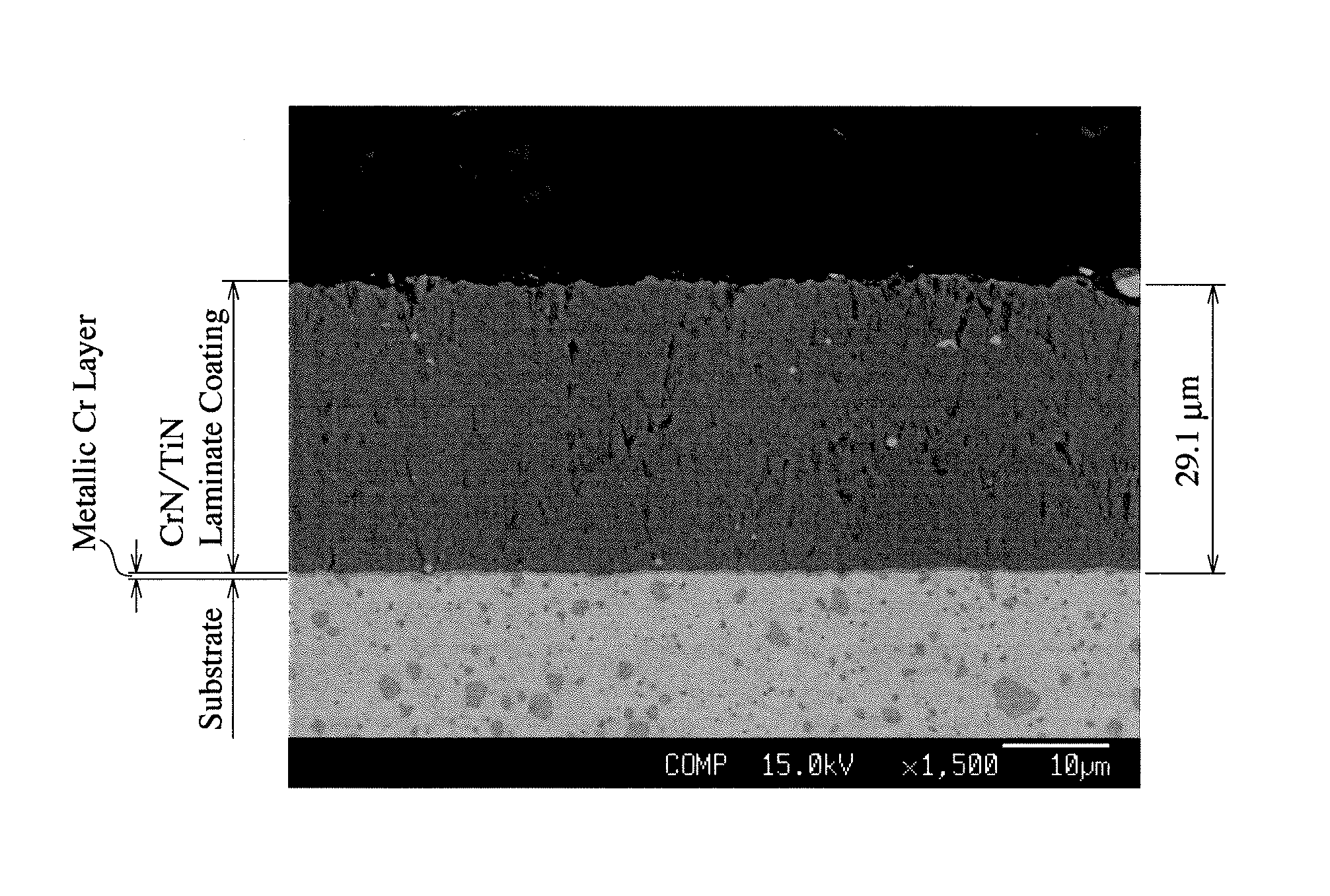
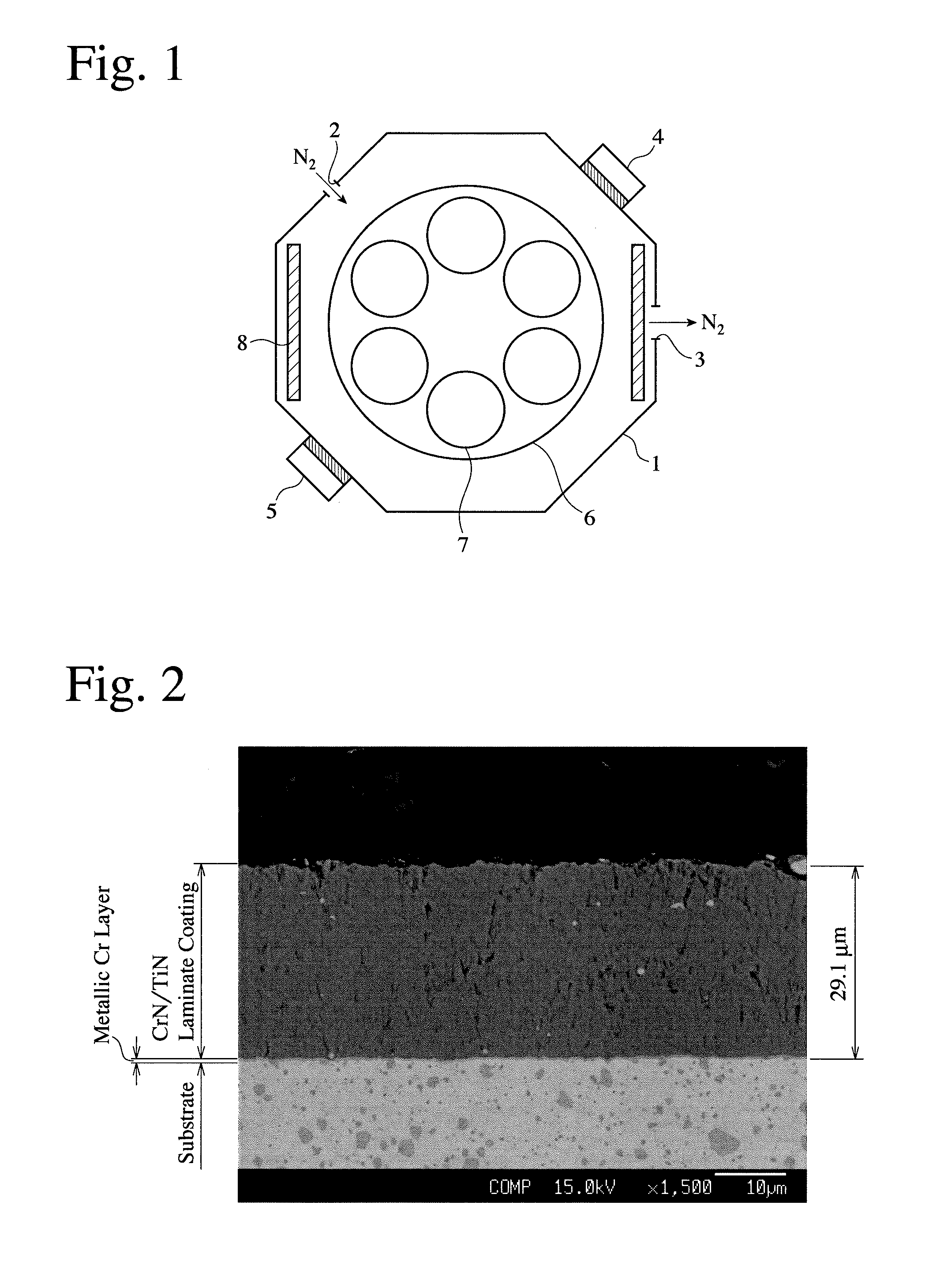
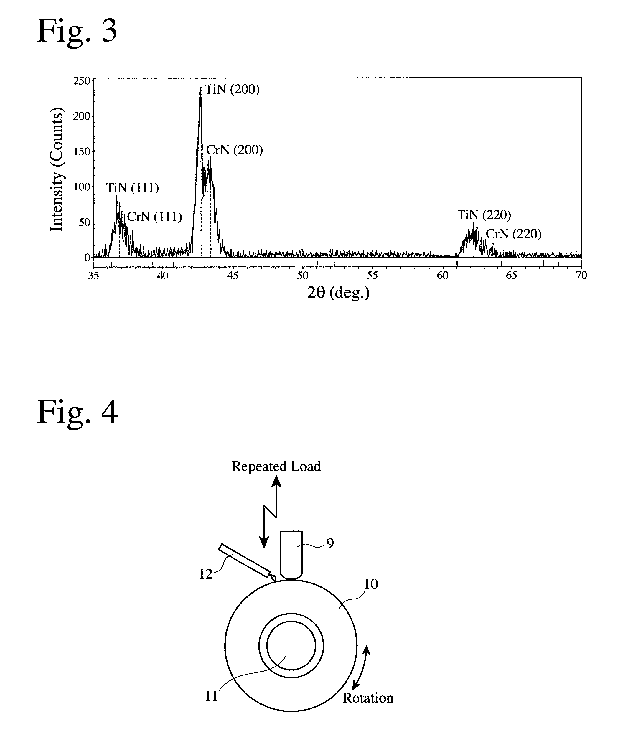
[0043]Piston rings each having a rectangular cross section and a barrel-faced outer peripheral surface [nominal diameter (d): 96 mm, thickness (al): 3.8 mm, and width (h1): 2.5 mm] were formed from a wire of SWOSC-V, and 50 piston rings were stacked, shot-blasted on their outer peripheral surfaces to surface roughness (Ry) of several μm, and set in an arc ion plating apparatus (AIP-S40 available from Kobe Steel, Ltd.), which had a target of 99.9-%-pure metallic chromium and a target of 99.9-%-pure metallic titanium. After evacuating the apparatus to 1.0×10⁻² Pa, outer peripheral surfaces of the piston rings as substrates were cleaned by a bombardment treatment, with an Ar gas introduced up to 1.0 Pa, and bias voltage of −600 V to −1000 V applied. The Ar gas was 99.99% pure. Thereafter, with a 99.999-%-pure N2 gas introduced up to 4 Pa, ion plating was conducted for 400 minutes, at arc current of 120 A for the metallic chromium cathode, arc current of 170 A for the metallic titanium ...

examples 2-8

[0057]In Examples 2-8, ion plating was conducted under the film-forming conditions shown in Table 1, which also shows the film-forming conditions in Example 1. In Example 2, a lower partial pressure of N2 than in Example 1 was used. In Example 3, a ratio of chromium to titanium was changed by changing arc current applied to the metallic chromium cathode and the metallic titanium cathode, and larger bias voltage than in Example 1 was used. In Examples 4 and 5, the number of rotation of the table was smaller than in Example 1 to change the thickness of a unit laminate. In Example 6, arc current applied to the metallic chromium cathode and the bias voltage were larger than in Example 4. In Example 7, the bias voltage was larger than in Examples 3 and 6. In Example 8, the bias voltage was smaller than in Example 3.

TABLE 1Film-ArcPartialBiasRotationFormingCurrent (A)Pressure ofVoltageof TableTimeNo.CrTiN2 (Pa)(V)(rpm)(minute)Example 11201704−92400Example 21201702.7−92370Example 31601304−...

examples 9-10

[0061]Ion plating was conducted in the same manner as in Example 1, except for changing the arc-ion-plating cathodes to the same metallic chromium cathode as in Example 1 and a 99.7-%-pure metallic zirconium cathode (Example 9), and to the same metallic chromium cathode as in Example 1 and a titanium-aluminum alloy (50 atomic % Ti-50 atomic % Al alloy) cathode (Example 10), thereby forming a CrN / ZrN laminate coating in Example 9 and a CrN / TiAlN laminate coating in Example 10 on piston rings. The arc current was 120 A at the metallic chromium cathode, 170 A at the metallic zirconium cathode, and 170 A at the titanium-aluminum cathode.


PUM

PropertyMeasurementUnit
thickaaaaaaaaaa
thicknessaaaaaaaaaa
crystallite sizeaaaaaaaaaa

Abstract

To provide a piston ring having a hard laminate coating for excellent scuffing resistance, wear resistance and peeling resistance, which can be used in an environment of high mechanical and thermal load in engines, the piston ring is provided with a hard laminate coating as thick as 10-60 μm on its outer peripheral surface, the laminate coating being formed by alternately laminating two types or more of layers made of different compounds, each of the compound layers being made of nitride of at least one metal selected from the group consisting of Ti, Cr, Zr, V, Hf and Al.

Description

FIELD OF THE INVENTION[0001]The present invention relates to a piston ring for automobile engines, particularly to a piston ring having hard laminate coating formed by ion plating for excellent scuffing resistance, wear resistance and peeling resistance.BACKGROUND OF THE INVENTION[0002]Piston rings have recently become used in increasingly severer environment, due to higher power of engines, higher combustion temperatures and larger load for meeting exhaust gas regulations, the use of low-viscosity lubricating oils, the diversification of fuels such as bioethanol, higher fuel injection pressure, etc. Even piston rings having hard chromium nitride (CrN) coatings formed by ion plating, which are now considered as having best scuffing resistance and wear resistance, may fail to exhibit sufficient performance due to the peeling of coatings by cracking and chipping. Accordingly, improvement in scuffing resistance, wear resistance and peeling resistance has been more strongly demanded tha...

Claims


Application Information

Patent Timeline
Patent Type & Authority Applications(United States)
IPC IPC(8): F16J9/26C23C14/06
CPCC23C14/0641F16J9/26C23C14/325C23C28/042C23C28/044C23C28/42F02F5/00
Inventor SATO, MASAYUKIMURAYAMA, YUUICHIIWAMOTO, YOUHEI
Owner RIKEN CO LTD
Why Eureka
Try Eureka