
Method and system for heat transfer

a heat exchanger and heat exchange technology, applied in the field of heat exchangers, can solve the problems of further reducing the efficiency and affecting the heat exchange rate of the heat exchanger, so as to reduce the cost, preserve heat and energy, and discharge water

Inactive Publication Date: 2005-02-15
THE BOEING CO
View PDF16 Cites 12 Cited by
  • Summary
  • Abstract
  • Description
  • Claims
  • Application Information

AI Technical Summary

Benefits of technology

One advantage of the invention is that a substantial portion, e.g. 90%, of the water is recycled thereby reducing the costs associated with supplying the water and discharging the water.
is that a substantial portion, e.g. 90%, of the water is recycled thereby reducing the costs associated with supplying the water and discharging the water.
Another advantage of the invention is that a substantial portion, e.g. 90%, of the heated water is recycled thereby preserving heat and energy and increasing the efficiency of the heat exchanger.
Still yet another advantage of the present invention a substantial portion, e.g. 90%, of the treated water is recycled thereby decreasing the amount of chemicals needed to maintain the water at a desirable pH level and decreasing costs associated therewith.

Problems solved by technology

Eventually, the accumulation of mineral deposits on heat transfer surfaces may reach a level that substantially impedes heat transfer.
In addition, the higher concentration of minerals may also result in corrosion of the heat exchanger thereby further decreasing the efficiency of the heat exchanger.
Although this process may successfully decrease the level of mineral deposits within the heat exchanger, it also typically introduces a variety of new problems.
One skilled in the art will understand that these problems usually include wasted energy, water, and chemicals used to treat the water.
In particular, energy typically is wasted because the discharged blowdown water has the same temperature as that of the steam generated in the boiler.
Additionally, water and chemicals are clearly wasted because the discharged blowdown water ordinarily is no longer reused by the heat exchanger.
A drawback of this proposed solution is that a relatively excessive amount of water still is ultimately discharged from the heat exchanger.
In particular, this proposed solution typically recycles only about 75% of the water for reuse by the heat exchanger.

Method used


Image

  • Method and system for heat transfer
  • Method and system for heat transfer

Examples


Embodiment Construction

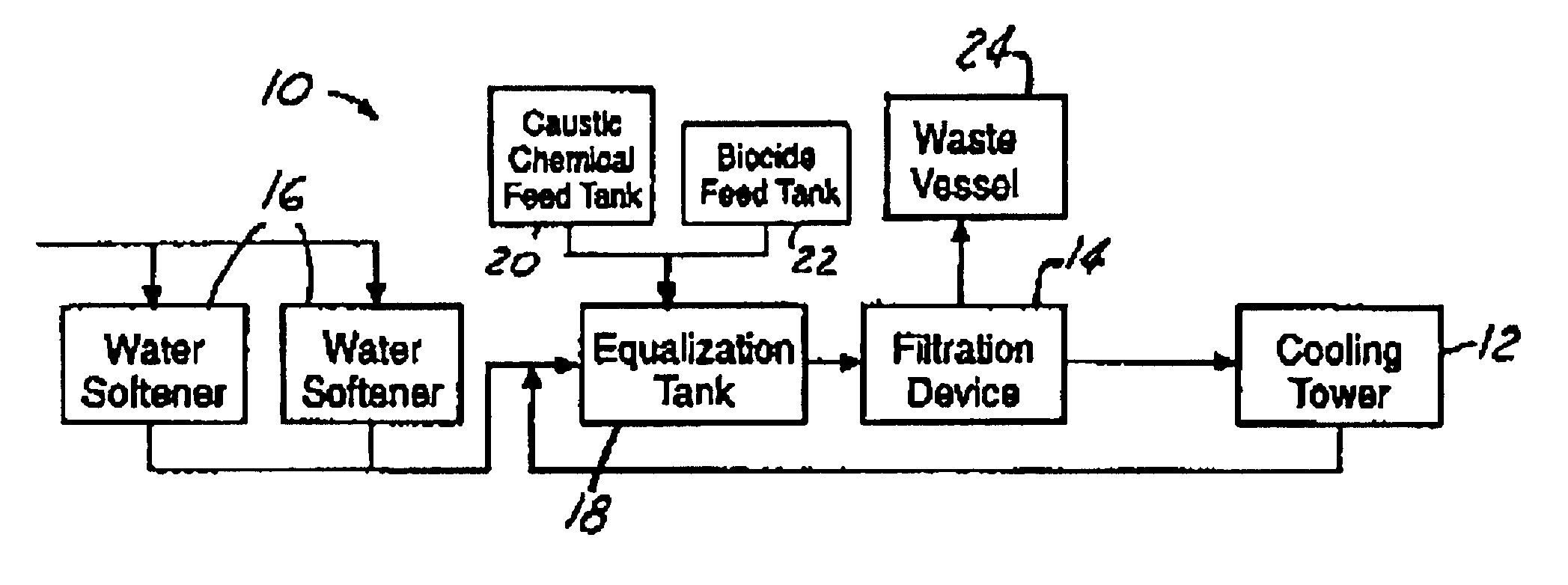
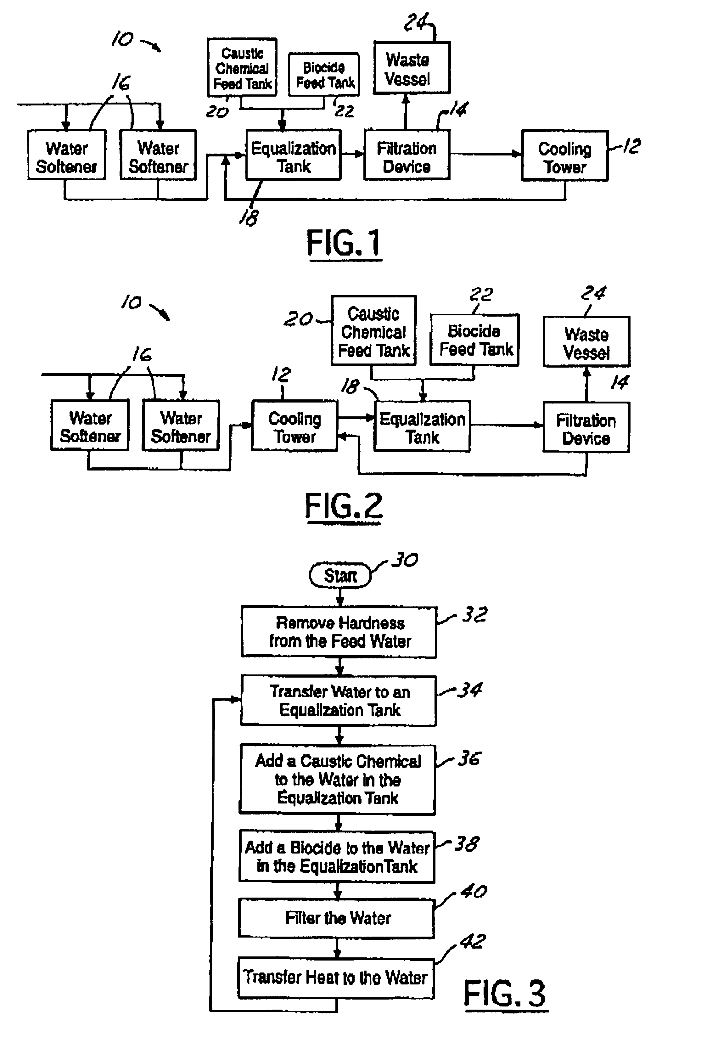
In the following figures the same reference numerals will be used to illustrate the same components in the various views. The present invention is particularly suited for a cooling tower 12. However, it is understood that the present invention may be utilized within a variety of other heat exchangers, such as boilers.

Referring to FIG. 1, there is shown a schematic diagram of a system 10 utilizing a filtration device 14 and a water softener 16 for pre-treating feed water and improving the efficiency of a cooling tower 12. Preferably, the system 10 includes two water softeners 16 for pre-treating the feed water before it is used to transfer heat within the cooling tower 12. However, it is understood that the system 10 may instead include only one water softener 16 or more than two water softeners 16 as desired.

The water softener removes hardness employing ion exchange technology. As one skilled in the art will understand, water softeners remove minerals, e.g. calcium and magnesium, fr...


PUM

PropertyMeasurementUnit
Volumeaaaaaaaaaa
Heataaaaaaaaaa
Hardnessaaaaaaaaaa

Abstract

A method and system (10) for utilizing water to transfer heat are provided. In one embodiment, the system (10) includes two water softeners (16) for removing the hardness of the feed water. The water softeners (16) are coupled to a filtration device (14) and deliver the softened water thereto. The filtration device (14) removes minerals from the water so as to produce a filtered water volume and a rejected water volume. The filtration device (14) delivers the filtered water volume to a heat exchanger (12). The heat exchanger (12) evaporates the filtered water volume and produces a mineral deposit volume. The mineral deposit volume is delivered to the filtration device (14) for removal of the mineral deposits so as to produce a recycled water volume and a blowdown water volume. Thereafter, the recycled water volume is delivered to the heat exchanger (12) for reuse, and the blowdown water volume is discharged to the waste vessel (24).

Description

TECHNICAL FIELDThe present invention relates generally to heat exchangers that utilize water for transferring heat, and more particularly to a method and system employing a reverse osmosis systems in combination with water softeners for improving heat transfer.BACKGROUND OF THE INVENTIONHeat exchangers that utilize water for transferring heat are well known. Two examples of these heat exchangers are boilers and cooling towers. As steam is produced by the boiler or as water evaporates from the cooling tower, mineral deposits are typically left behind. Ordinarily, more minerals are introduced by way of the water added to make up for the water lost to steam or evaporation. Eventually, the accumulation of mineral deposits on heat transfer surfaces may reach a level that substantially impedes heat transfer. In addition, the higher concentration of minerals may also result in corrosion of the heat exchanger thereby further decreasing the efficiency of the heat exchanger.One proposed solut...

Claims


Application Information

Patent Timeline
IPC IPC(8): C02F9/00F28F25/00F28F19/00C02F1/78C02F1/04C02F1/66C02F1/44C02F1/42C02F1/50C02F1/76C02F5/00F22B37/54B01D61/02B01D65/08F22D11/00F28G13/00
CPCB01D61/025F28F25/00F28F19/00C02F9/00C02F1/04C02F2303/08C02F2103/023C02F2001/422C02F1/42C02F1/441C02F1/50C02F1/66C02F1/76C02F1/78C02F5/00
Inventor BONDS, ROBERT JAYBESHALER, JR., JAMES A.SIZEMORE, DAVID R.
Owner THE BOEING CO
Learn More