
Binding protein as biosensors

a technology of binding protein and biosensor, which is applied in the field of biotechnology, can solve the problems of inability to bind to the associated reporter group, difficulty in patient compliance, and influence of oxygen level,

Inactive Publication Date: 2005-02-15
BECTON DICKINSON & CO
View PDF34 Cites 90 Cited by
  • Summary
  • Abstract
  • Description
  • Claims
  • Application Information

AI Technical Summary

Benefits of technology

The invention provides a glucose biosensor that can detect glucose levels in the body. It includes a mutated protein that changes its signal when exposed to different glucose concentrations. The biosensor can be used in vivo or in vitro. The invention also provides a method for glucose detection by exposing the mutated protein to varying glucose concentrations and detecting the resulting signal change. The mutated protein has certain amino acid substitutions that enhance its glucose-binding ability. The invention also provides compositions containing the mutated protein with specific amino acid substitutions.

Problems solved by technology

Currently, most diabetics use the “finger stick” method to monitor their blood glucose levels and patient compliance is problematic due to pain caused by frequent (several times per day) sticks.
This method is associated with difficulties including the influence of oxygen levels, inhibitors in the blood and problems with electrodes.
In addition, detection results in consumption of the analyte that can cause difficulties when measuring low glucose concentrations.
However this mutant protein and the associated reporter group do not bind diagnostically important sugars in mammalian bodily fluids.
Specific mutations of sites and / or attachment of certain reporter groups may act to modify a binding constant in an unpredictable way.
Additionally, a biosensor containing reporter groups may have a desirable binding constant, but not result in an easily detectable signal change upon analyte binding.
It is not currently possible to predict these interactions within proteins using existing computational methods, nor is it possible to employ rational design methodology to optimize the choice of reporter probes.
It is currently not possible to predict the effect on either the binding constant or the selectivity based on the position of any reporter group, or amino acid substitution in the protein (or visa-versa).
Therefore, problems result including an inability to maintain calibration of the sensing device and signal drift.
In general, binding proteins require orientational control to enable their use, thus physical absorption and random or bulk covalent surface attachment or immobilization strategies as taught in the literature generally are not successful.

Method used


Image

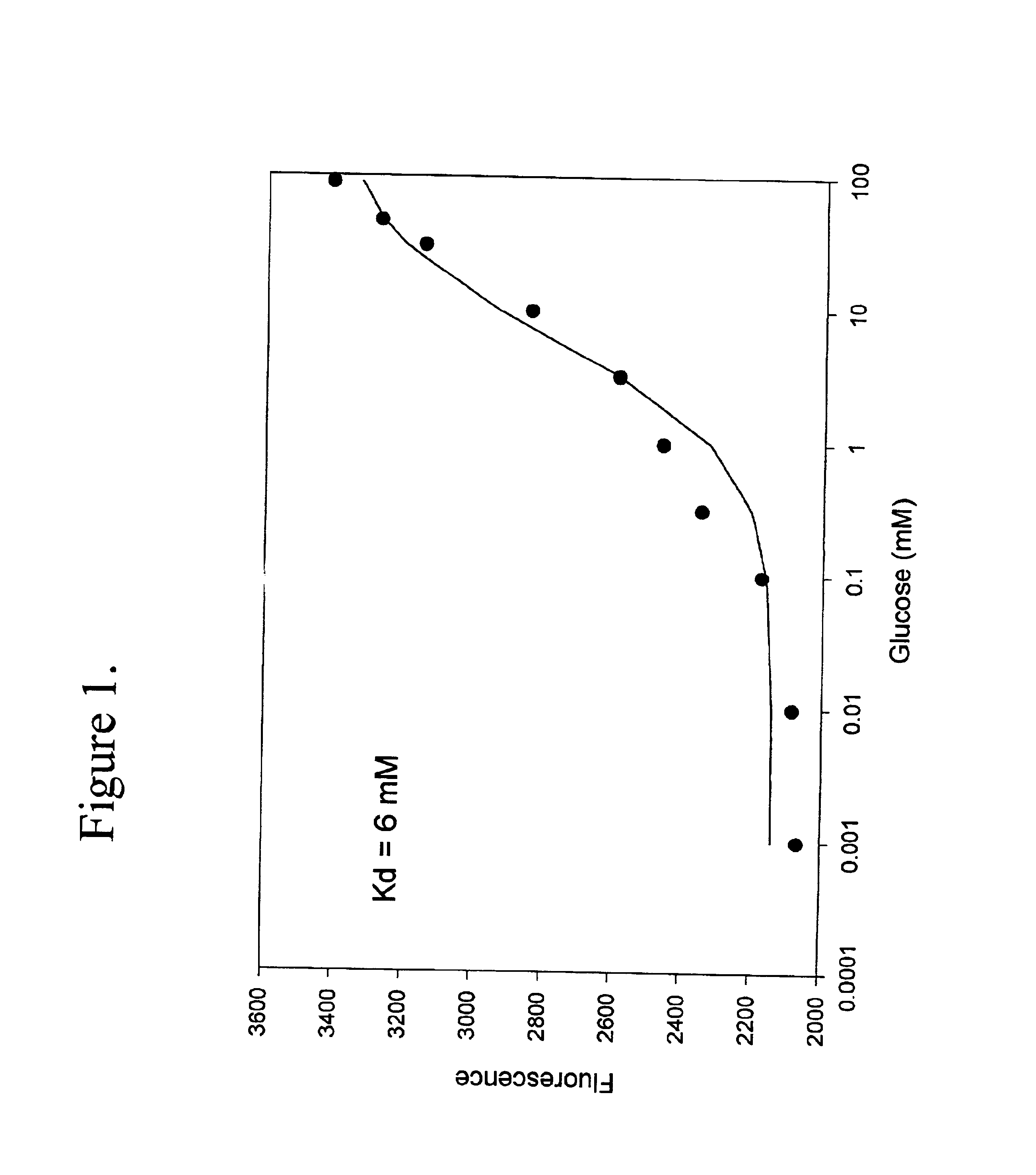
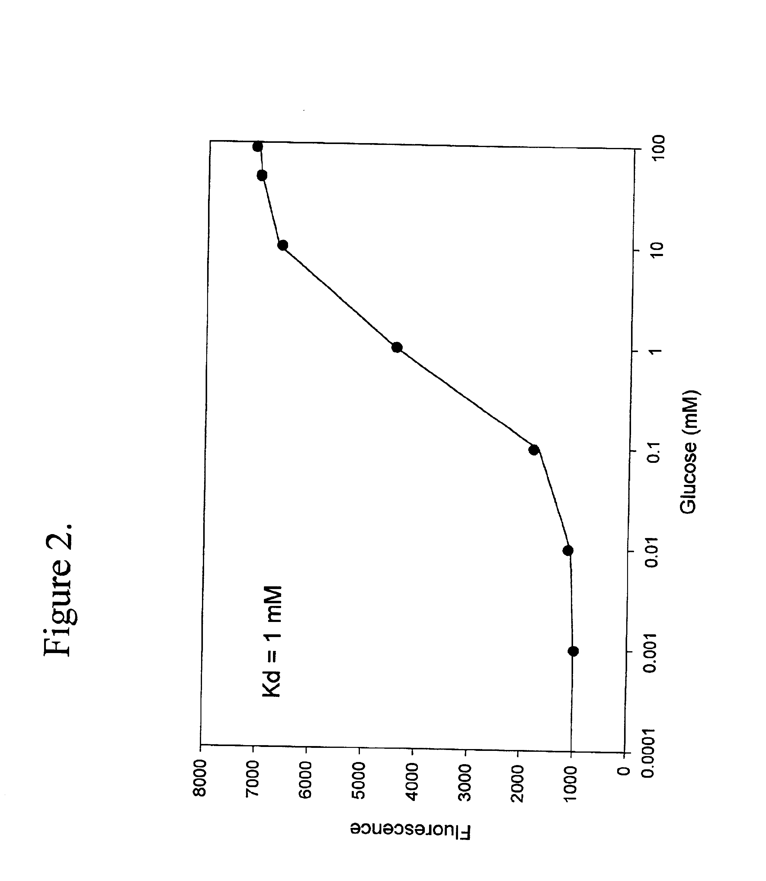
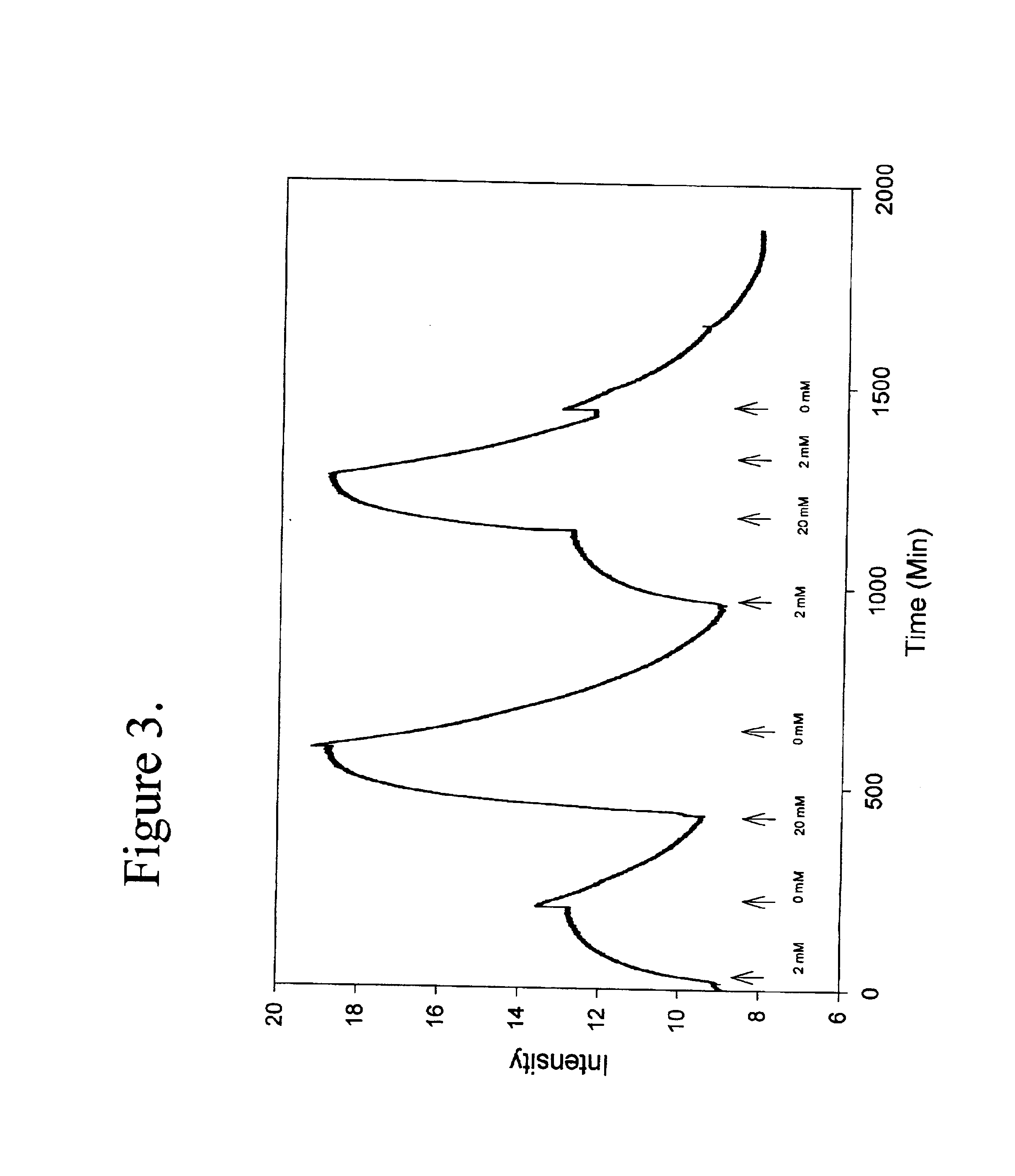
  • Binding protein as biosensors
  • Binding protein as biosensors
  • Binding protein as biosensors

Examples


Embodiment Construction

The term biosensor generally refers to a device that uses specific biochemical reactions mediated by isolated enzymes, immunosystems, tissues, organelles or whole cells to detect chemical compounds, usually by electrical, thermal or optical signals. As used herein a “biosensor” refers to a protein capable of binding to an analyte which may be used to detect an analyte or a change in analyte concentration by a detector means as herein described.

The term “binding proteins” refers to proteins which interact with specific analytes in a manner capable of providing or transducing a detectable and / or reversible signal differentiable either from when analyte is not present, analyte is present in varying concentrations over time, or in a concentration-dependent manner, by means of the methods described herein. The transduction event includes continuous, programmed, and episodic means, including one-time or reusable applications. Reversible signal transduction may be instantaneous or may be t...


PUM

PropertyMeasurementUnit
excitation wavelengthaaaaaaaaaa
emission wavelengthaaaaaaaaaa
emmision wavelengthsaaaaaaaaaa

Abstract

The invention is directed to compositions of mutated binding proteins containing reporter groups, analyte biosensor devices derived there from, and their use as analyte biosensor both in vitro and in vivo.

Description

BACKGROUND OF THE INVENTION1. Field of the InventionThe invention is in the field of biotechnology. Specifically, the invention is directed to compositions of mutated binding proteins containing reporter groups, analyte biosensor devices derived there from, and their use as analyte biosensors both in vitro and in vivo.2. Description of Relevant ArtMonitoring glucose concentrations to facilitate adequate metabolic control in diabetics is a desirable goal and would enhance the lives of many individuals. Currently, most diabetics use the “finger stick” method to monitor their blood glucose levels and patient compliance is problematic due to pain caused by frequent (several times per day) sticks. As a consequence, there have been efforts to develop non-invasive or minimally invasive in vivo and more efficient in vitro methods for frequent and / or continuous monitoring of blood glucose or other glucose-containing biological fluids. Some of the most promising of these methods involve the u...

Claims


Application Information

Patent Timeline
Patent Type & Authority Patents(United States)
IPC IPC(8): C07K14/245C07K14/195G01N33/543G01N33/53G01N21/78G01N33/566G01N33/58
CPCC07K14/245G01N33/5438Y10T436/144444Y10S435/817
Inventor AMISS, TERRY J.NYCZ, COLLEEN M.PITNER, J. BRUCESHERMAN, DOUGLAS B.WRIGHT, DAVID J.
Owner BECTON DICKINSON & CO
Learn More