
Card edge connector, method of manufacturing same, electronic card and electronic equipment

a technology of edge connectors and edge plates, applied in the direction of resist details, instruments, non-metallic protective coating applications, etc., can solve the problems of difficulty in insertion of connectors, damage to connector portions, and breakage of prismatic edges, so as to prevent the occurrence of electrical short circuits, facilitate the insertion and extraction operation, and facilitate the manufacturing

Inactive Publication Date: 2005-02-15
FUJITSU LTD
View PDF11 Cites 23 Cited by
  • Summary
  • Abstract
  • Description
  • Claims
  • Application Information

AI Technical Summary

Benefits of technology

It is a first object of the present invention to provide a card edge connector which requires a smaller force than before for insertion and extraction and therefore permits insertion and extraction operation to be carried out easily, and which does not give rise to broken debris of component members during such an operation and can thus prevent occurrence of an electrical short circuit due to such a debris, and which can be manufactured easily and at a low cost.
It is another object of the present invention to provide a method of making such a card edge connector in a simple manner and at a low cost and with a high yield.
It is still another object of the present invention to provide an electronic card which permits insertion and extraction operation to be carried out easily, and which does not give rise to a broken debris of component members during such an operation and can thus prevent occurrence of an electrical short circuit due to such a debris.
It is a further object of the present invention to provide an electronic equipment comprising an electronic card which permits insertion and extraction operation to be carried out easily, and which does not give rise to broken debris of component members during such an operation and can thus prevent occurrence of an electrical short circuit due to such a debris.

Problems solved by technology

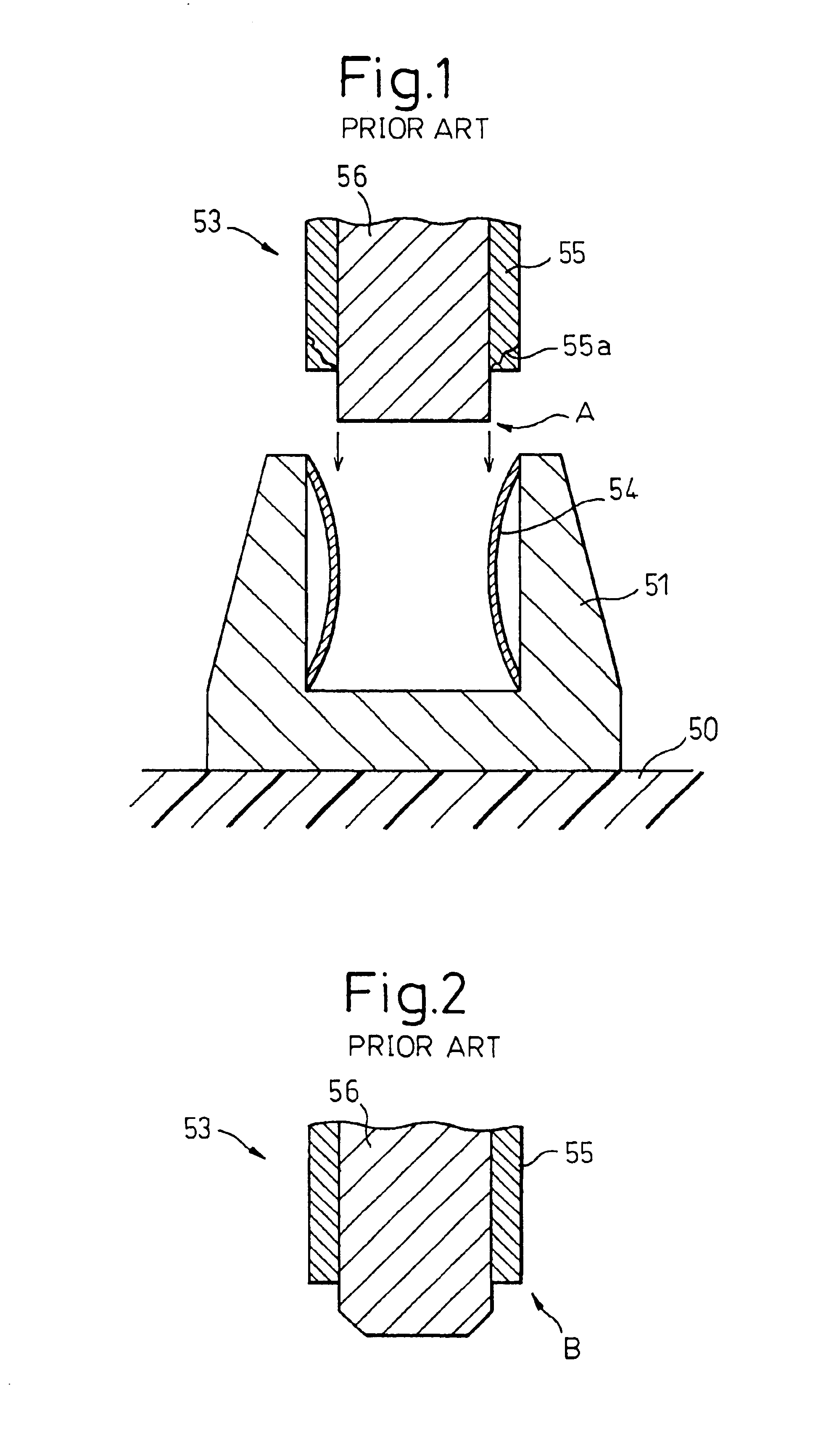
In the case of the card edge connector 53 as shown in FIG. 1, however, a large force is required for insertion into and extraction from the connector, and this may sometime cause damage to the connector portion due to excessive force exerted in the operation.
However, in the card edge connector 53 as shown in FIG. 2, the terminating portions of the electrode contacts 55 are of a prismatic shape as shown by an arrow B so that difficulties may arise in the insertion of the connector, and problems may often arise in the insertion and extraction of the connector such as separation of the contacts, breaking of the prismatic edge and the falling-off of fine metal debris.
When the fine metal debris of the electrode contacts enters into inside of the electronic equipment, serious problems, for example, an electrical short circuit or the like, may arise.
Although it has been proposed to form the electrode contacts 55 as a thin film deposited on the card edge connector 53 in order to avoid the falling-off of metal debris, this method is not a feasible solution because, with increase of the amount of information processed, current electronic equipment is generally required to be able to pass a correspondingly large current.
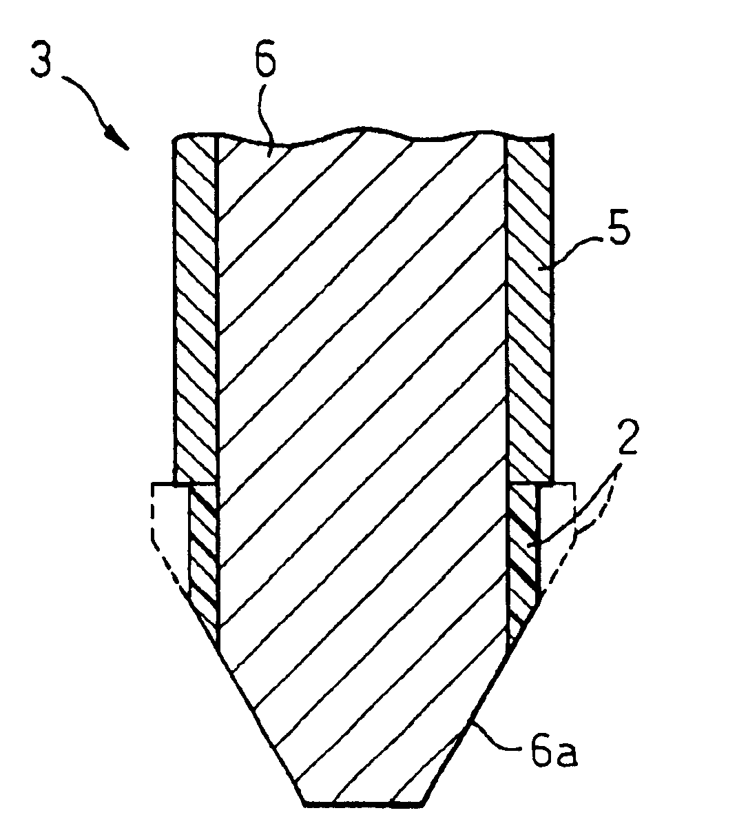
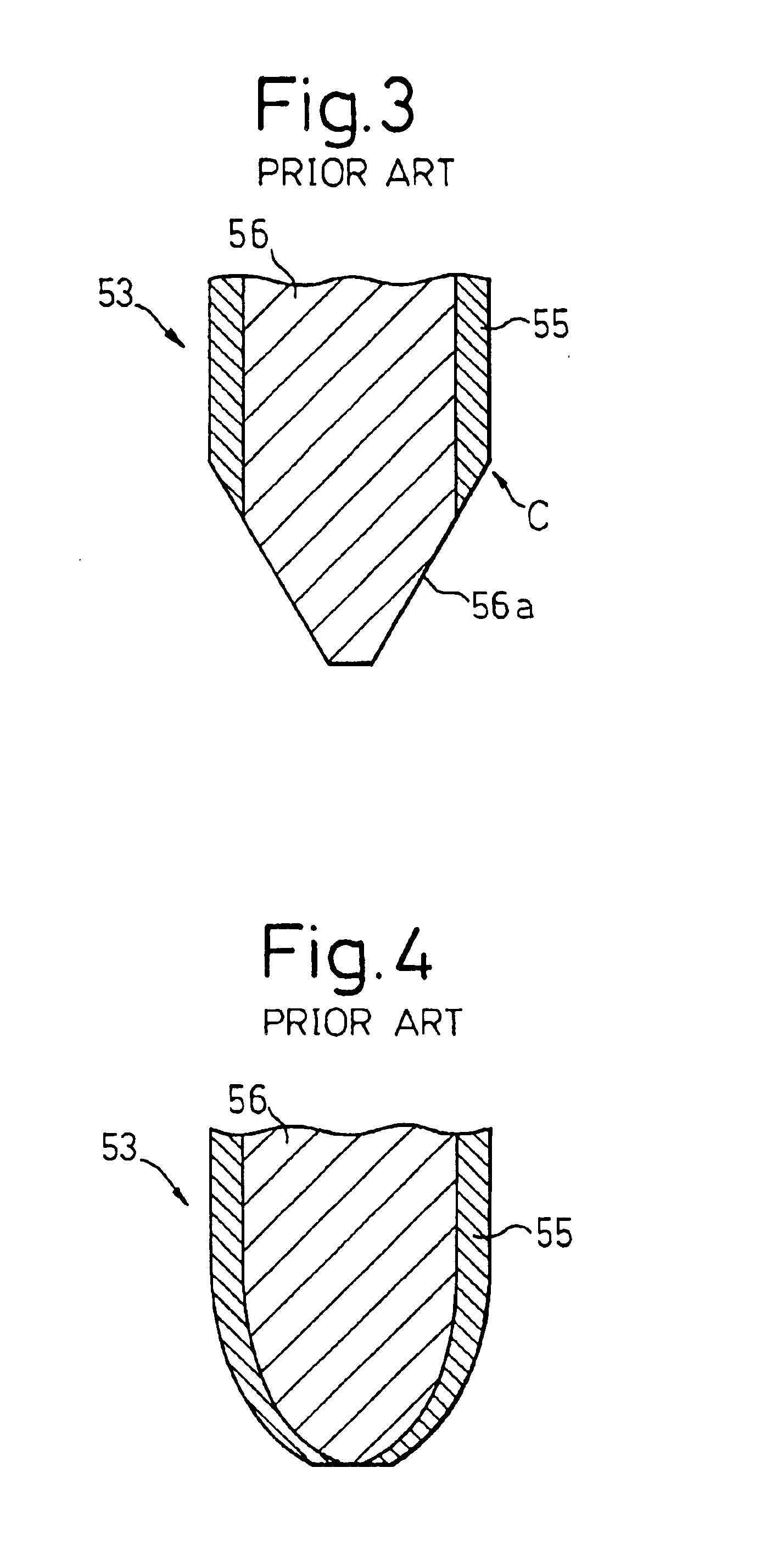
However, in cutting of the electrode contacts 55, burrs may arise in the corner portion shown by an arrow C, giving rise to another problem that a finishing operation to remove the burrs is necessary.
Also, in the case of a card edge connector of such a construction, the inclined surface 56a formed by the cutting is a rough surface so that repeated insertion and extraction of the connector tends to damage the connector contacts 55.
However, in the case of this card edge connector, multiple steps are required in the manufacturing process, and the manufacturing operation becomes very complicated leading, inevitably, to an increase in cost.

Method used


Image

  • Card edge connector, method of manufacturing same, electronic card and electronic equipment
  • Card edge connector, method of manufacturing same, electronic card and electronic equipment
  • Card edge connector, method of manufacturing same, electronic card and electronic equipment

Examples


Embodiment Construction

As has been described above, the present invention resides in a card edge connector for electrical connection and a method of manufacturing the same, and to an electronic card and an electronic equipment comprising the card edge connector of the invention.

The card edge connector of the present invention is used for inserting and fitting an electronic card, e.g. a memory card, having an electronic device such as a LSI chip packaged thereon, into a connector provided on a substrate such as a mother board of a semiconductor apparatus so as to establish electrical connection between the electronic card and the semiconductor apparatus.

As used herein, the term “electronic device” means various devices generally mounted on a semiconductor apparatus or other apparatus, specifically including, but not limited to, a semiconductor device such as an IC chip and a LSI chip, a capacitor, a transformer, a choke coil, a printed board, etc. An electronic device in its broad sense includes attached w...


PUM


Abstract

A card edge connector comprises a connector body and a conductive pad, and is constructed such that the conductive pad terminates at a predetermined distance from the end of the tip portion of the connector body, and that there is further provided a protective pad, adjacent to the terminating portion of the conductive pad, which is formed at the same time with the formation of a wiring pattern in a post-fabrication step of the wiring pattern. Using the card edge connector, an electric card and an electric equipment are also provided.

Description

BACKGROUND OF THE INVENTION1. Field of the InventionThe present invention relates to a card edge connector and, more particularly, to a card edge connector used for inserting and fitting an electronic card, that has an electronic device packaged thereon, into a connector of an electronic equipment. The present invention also relates to a method of manufacturing the, card edge connector, and to an electronic card and an electronic equipment using the card edge connector.2. Description of Related ArtAs is well known in the art, when a card-shaped printed circuit board is to be implemented in an electronic equipment, a generally adopted method is to provide a card edge connector at an end portion of the printed circuit board, and to insert and fit the card edge connector into a connector of the electronic equipment.FIG. 1 is a sectional view showing an example of a prior art card edge connector and illustrating the use thereof. In the illustrated example, a construction is adopted such...

Claims


Application Information

Patent Timeline
Patent Type & Authority Patents(United States)
IPC IPC(8): H05K1/11H05K3/34G06K19/067H01R43/00H05K1/02H05K3/28
CPCH05K1/117H01R12/721H05K3/3452H05K2201/09154H05K2201/098H05K2201/10863H05K2203/0594H01R12/714H05K2201/09909
Inventor EGUCHI, SUSUMUSHIMAMORI, HIROSHI
Owner FUJITSU LTD
Learn More