Voice coil linear actuator, apparatus using the actuator, and method for manufacturing the actuator

a technology of linear actuators and actuators, which is applied in the direction of electrical transducers, dynamo-electric machines, electrical apparatus, etc., can solve the problems of increasing the amount of heat generated, thermal deformation, and deterioration of magnets, so as to reduce the size, accelerate and decelerate, and increase the speed of parts mounting actions and the like

Inactive Publication Date: 2005-02-15
MURATA MFG CO LTD
View PDF7 Cites 14 Cited by
  • Summary
  • Abstract
  • Description
  • Claims
  • Application Information

AI Technical Summary

Benefits of technology

With the voice coil linear actuator according to the present invention, multiple magnetic circuits are formed in the axial direction by permanent magnets which are distributed in at least three positions in the axial direction, so magnetic resistance can be reduced as compared to conventional arrangements wherein there is only one primary magnetic circuit formed by permanent magnets, so higher thrust can be obtained with the same amount of coil. In other words, the same amount of thrust can be obtained with less coil. Also, particularly high magnetic flux density can be obtained due to the primary magnetic circuits being added. That is, the magnetic flux density corresponding to the positions of the permanent magnets sandwiched between opposite magnetic poles becomes extremely great. Accordingly, magnetic flux density is improved by more than enough to offset reduction in size of the overall actuator, so that not only can deterioration in thrust be suppressed, but also, increased thrust can be realized.
The parts assembling apparatus according to the present invention comprises: a parts supply unit upon which supplied parts may be loaded; a parts mounting unit where a supplied article upon which the parts are to be mounted may be loaded; the above-described parts mounting head picks up parts from the parts supply unit and mounts the parts on the article upon which the parts are to be mounted which is loaded on the parts mounting unit; and a head driving unit drives the parts mounting head. With the parts assembling apparatus according to the present invention, the speed of parts mounting actions and the like can be increased.

Problems solved by technology

However, applying a great current to the coil increases the amount of heat generated at the coil, causing problems such as thermal deformation in the surrounding members, deterioration of the magnet due to the heat, and so forth.
However, attempts to reduce the size of conventional voice coil linear actuators have had the following problems.
Accordingly, obtaining high magnetic flux density is difficult, and great thrust cannot be obtained.
Accordingly, obtaining high magnetic flux density becomes even more difficult.
However, the effects thereof are limited, and there has also been the problem that this arrangement is difficult to assemble.

Method used


Image

  • Voice coil linear actuator, apparatus using the actuator, and method for manufacturing the actuator
  • Voice coil linear actuator, apparatus using the actuator, and method for manufacturing the actuator
  • Voice coil linear actuator, apparatus using the actuator, and method for manufacturing the actuator

Examples


first embodiment

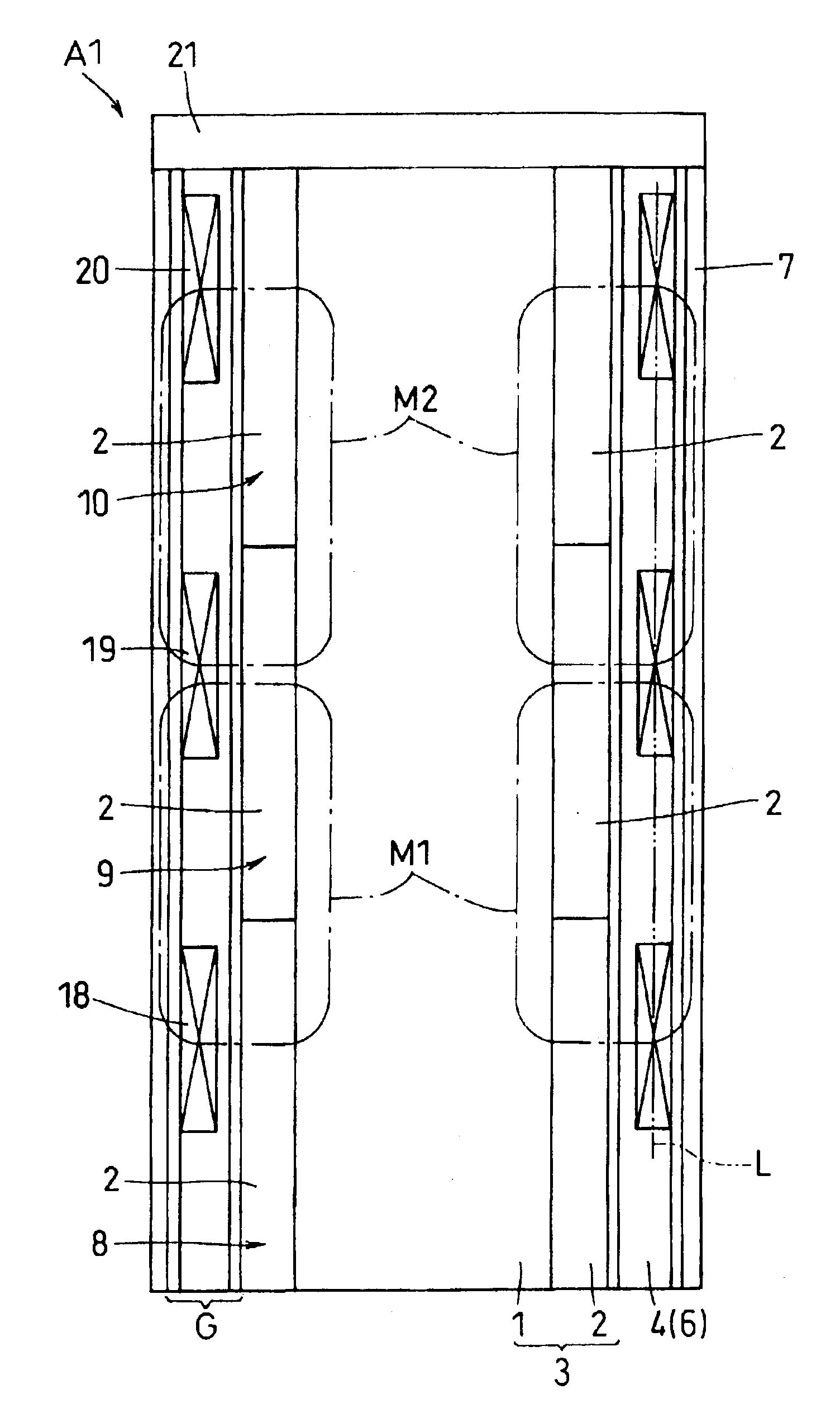
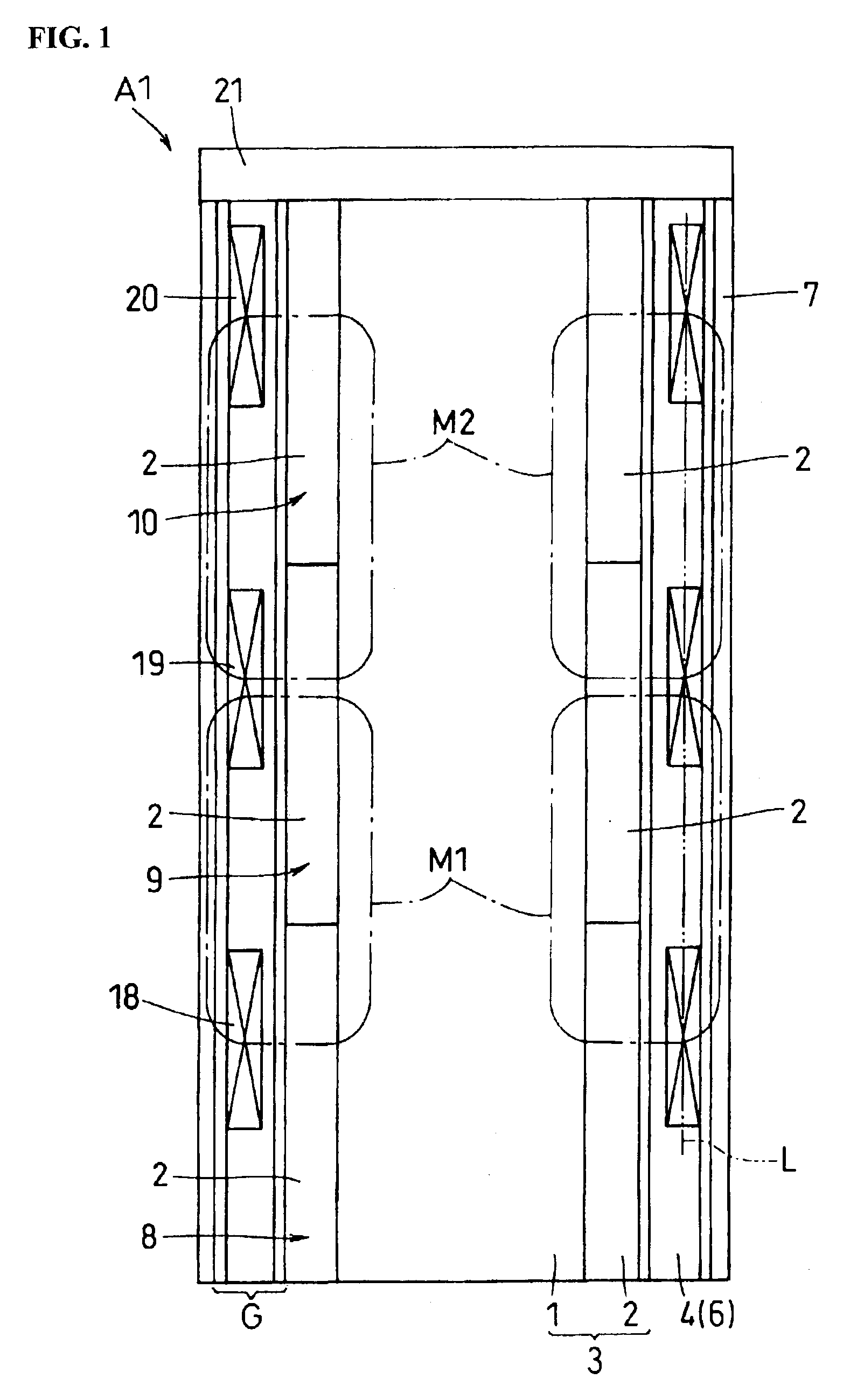
FIGS. 1 through 10 and FIG. 20 illustrate a first embodiment. FIG. 1 is a vertical-section view of a voice coil linear actuator according to a first embodiment of the present invention, FIG. 2 is an exploded perspective view of the voice coil linear actuator, FIG. 3 is a cross-sectional view of the voice coil linear actuator, FIG. 4 is a vertical-section view of the voice coil linear actuator with a linking member linked, FIG. 5 is a perspective view of an armature coil with a coil wire wound, FIG. 6 is a perspective view of a bobbin, FIGS. 7A and 7B are a cross-sectional views illustrating the positional relation between the magnet and armature coil unit formed of coil wire, FIG. 8 is an explanatory diagram illustrating the process for winding the coil wire onto the bobbin, FIG. 9 is a perspective view of a modification of a bobbin, and FIG. 10 is a schematic side view illustrating a mounting head. Also, FIG. 20 is a schematic vertical-sectional diagram illustrating one half of a v...

second embodiment

Next, a second embodiment of the voice coil linear actuator according to the present invention will be described with reference to FIGS. 11 through 13 and others. The structures which are the same as those in the above-described first embodiment will be denoted with the same reference numerals, and illustrations in the drawings which are in common between the first and second embodiments will be described with reference to the drawings referred to with the first embodiment. Now, FIG. 11 is a schematic vertical-sectional diagram of the voice coil linear actuator indicating the dimensions of the components. FIG. 12 is a vertical-sectional diagram illustrating the voice coil linear actuator, and FIG. 13 is a graph illustrating the relation between the axial position on the voice coil linear actuator and the magnetic flux density.

With reference to FIG. 12, the voice coil linear actuator A2 comprises a center stator 3, an armature coil 6, and an outer yoke 7.

In detail, the armature coil ...


PUM


Abstract

A voice coil linear actuator comprises: an axially-shaped center yoke formed of a ferromagnetic material; an armature coil concentrically disposed so as to move along the axial direction of the center yoke; and a plurality of ring-shaped permanent magnets which have N and S magnetic poles arranged in the radial direction thereof, and are disposed concentrically as to the armature coil. The armature coil has armature coil units distributed in at least three positions in the axial direction, with adjacent pairs of the armature coil units being arranged so that electric current flows through them in opposite directions, respectively. The permanent magnets are distributed in at least three positions in the axial direction at positions facing respective armature coil units in the radial direction. The respective directions of the N magnetic poles of adjacent permanent magnets are arranged facing in opposite directions.

Description

BACKGROUND OF THE INVENTION1. Field of the InventionThe present invention relates to a voice coil linear actuator, an apparatus using the actuator, and a method for manufacturing the actuator.2. Description of the Related ArtVoice coil linear actuators are used in arrangements wherein linear actions are performed for relatively short distances, such as with a mounting head of an electronic parts mounting apparatus, for example.Generally, voice coil linear actuators generate thrust by mutual action between a magnetic field from a magnet and an electric current flowing through a coil, and there are two general arrangements for this. One is an arrangement wherein the magnet is fixed and the coil moves, and the other is an arrangement wherein the coil is fixed and the magnet moves.Arrangements disclosed in Japanese Unexamined Patent Application Publication No. 11-299210 and Japanese Unexamined Patent Application Publication No. 11-69755, for example, are known arrangements of the coil m...

Claims


Application Information

Patent Timeline
Patent Type & Authority Patents(United States)
IPC IPC(8): H02K41/035H02K33/18H04R9/06
CPCH04R9/063H02K41/0356
Inventor HIRATA, ATSUHIKO
Owner MURATA MFG CO LTD
Why Eureka
Try Eureka