
Converter for converting an AC power main voltage to a voltage suitable for driving a lamp

a technology of alternating current and power main voltage, which is applied in the direction of light sources, lighting devices, instruments, etc., to achieve the effects of avoiding high-cost tantalum capacitors, precise control of output current, and improved reliability

Inactive Publication Date: 2005-02-15
ECLAIRAGE CONTRASTE M L
View PDF11 Cites 12 Cited by
  • Summary
  • Abstract
  • Description
  • Claims
  • Application Information

AI Technical Summary

Benefits of technology

A further advantage of the invention is an avoidance of high cost tantalum capacitors, and improved reliability at high temperature operation.
is an avoidance of high cost tantalum capacitors, and improved reliability at high temperature operation.
Another advantage of the invention is a precise control of output current in addition to protection against fault conditions, such as output short circuits.
A further advantage of the invention is an extended operational temperature range for the converter, which enables the converter to achieve an Underwriters Laboratories (UL) Class B temperature classification up to 130° C., which is a maximum insulation limitation.
Yet another advantage of the invention is providing a converter with an operating frequency that is greater than 30 kHz, which enables smaller converter packages and more power efficient converters especially when output rectification is MOSFET synchronous.
Still another advantage of the invention relates to decreased current leakage and switching losses at elevated temperature resulting from the use of MOSFET (metal oxide silicon field-effect) transistors for switching drive current and rectifying output current.

Problems solved by technology

This causes the output current limiting signal to reduce output current from the driver circuit when the converter overheats.

Method used


Image

  • Converter for converting an AC power main voltage to a voltage suitable for driving a lamp
  • Converter for converting an AC power main voltage to a voltage suitable for driving a lamp
  • Converter for converting an AC power main voltage to a voltage suitable for driving a lamp

Examples


Embodiment Construction

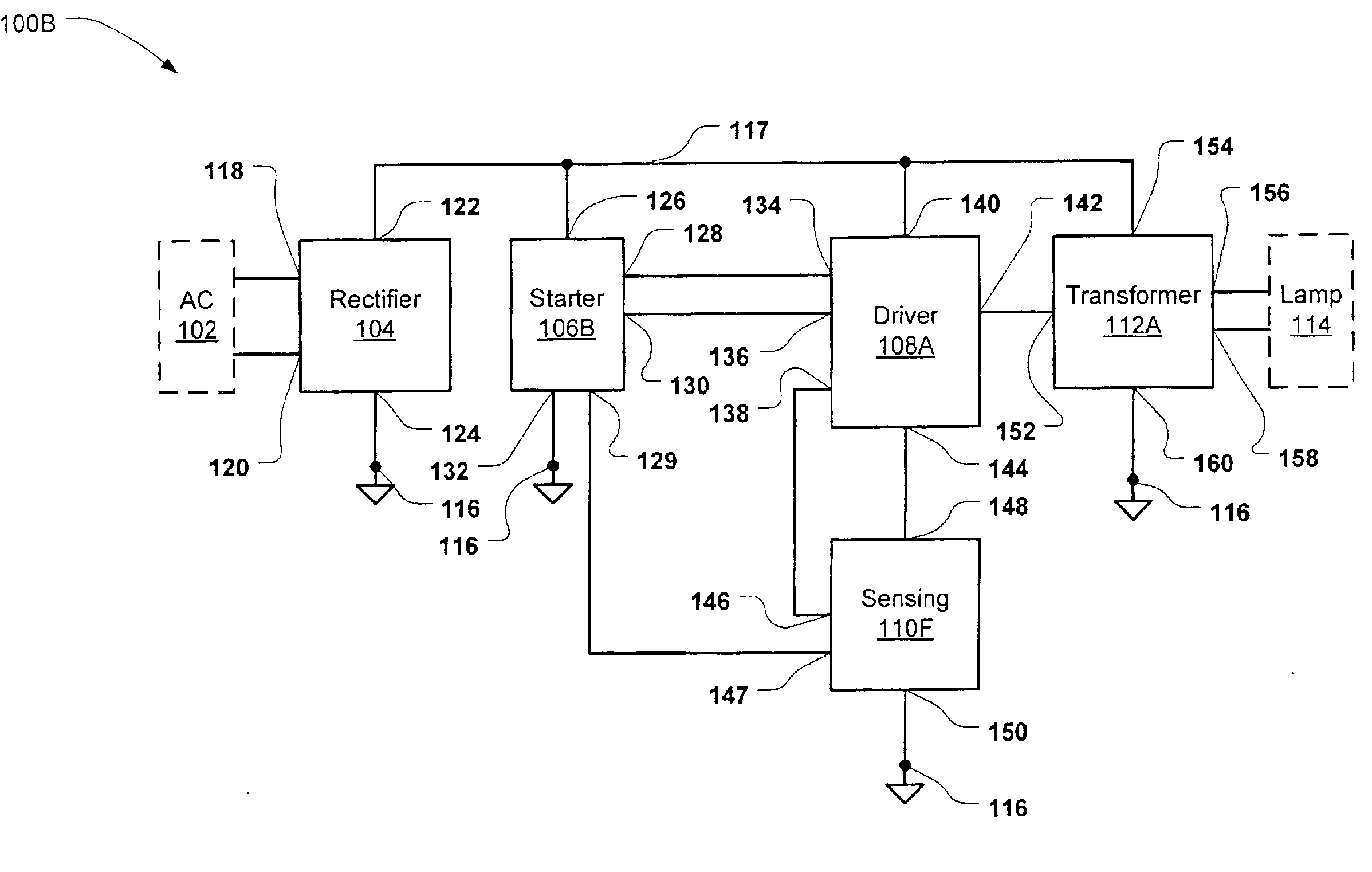
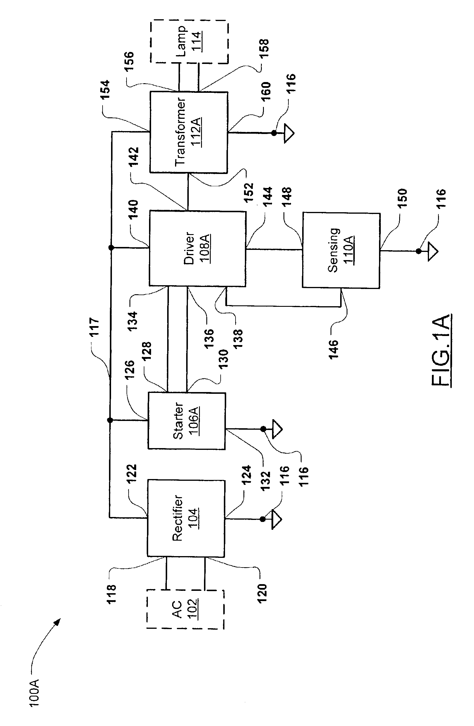
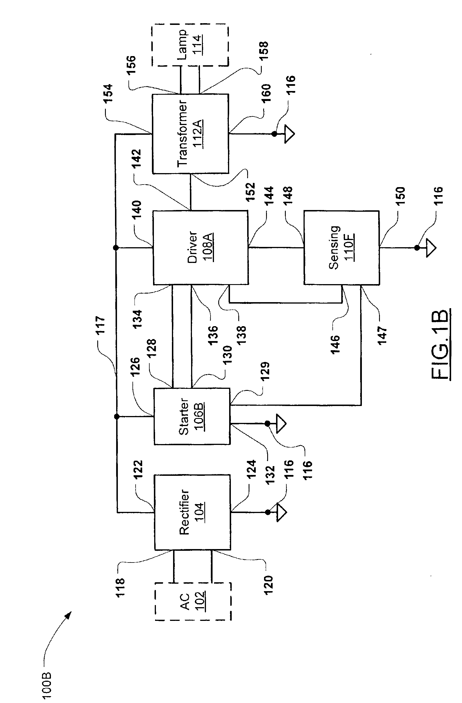
FIG. 1A illustrates a converter 100A in accordance with the invention. The converter 100 includes a rectifier circuit 104, a starter circuit 106A, a driver circuit 108A, a sensing circuit 110A, and a transformer circuit 112A. The rectifier circuit 104 has a first and second input 118,120 connectable to an AC (alternating current) power main 102 (shown in dotted outline), a first terminal 122 connected to a power supply node 117 and a second terminal 124 connected to a ground reference node 116. The starter circuit 106A has a first terminal 126 connected to power supply node 117, a second terminal 132 connected to ground reference node 116, a clamp output 128, and a starter output 130. The driver circuit 108A has a first output 134 connected to the clamp output 128 of starter circuit 106A, a first input 136 connected to the starter output 130 of starter circuit 106A, a second input 138, a first terminal 140 connected to the power supply node 117, a second output 142 and a second term...


PUM


Abstract

An electronic converter converts high-voltage AC power main voltage, such as 120V, 240V or 277V, to a low-voltage suitable for driving a halogen lamp. The converter includes a rectifier circuit, starter circuit, a driver circuit, a current sensing circuit and a transformer circuit with an optional synchronous output rectifier. The current sensing circuit senses an output current of the converter. The sensed current is used to govern pulse-width modulation of the lamp drive voltage, to provide over-voltage protection. Temperature protection can also be provided to reduce drive current when the converter overheats. This enables reliable operation of the converter over an extended temperature range, and reduces the occurrence of converter component failures due to ground faults or overheating.

Description

TECHNICAL FIELDThe present invention relates to converters for converting alternating current (AC) power main voltage to a voltage suitable for driving a lamp.BACKGROUND OF THE INVENTIONMost electronic converters for converting AC power main voltage to a voltage for driving a lamp, such as a halogen lamp, are based on self-oscillating technology using bipolar transistors. Since bipolar transistors are current operating devices, obtaining feedback for oscillation is relatively simple. However, bipolar transistor converters with or without diode rectification suffer from several disadvantages. For example they are subject to secondary breakdown phenomena, increased current leakage and increased power losses at elevated temperatures. The practical limit for junction temperature is 100° C. (case temperature typically 85° C.). Bipolar transistor converters are also expensive for high voltage applications (for example 277V, 240V and 220V). They also are less efficient in operation than fi...

Claims


Application Information

Patent Timeline
IPC IPC(8): H05B41/285H05B41/28
CPCH05B41/2856
Inventor PIASKOWSKI, ANDREW D.
Owner ECLAIRAGE CONTRASTE M L
Learn More