Magnetic sensor, side-opened TEM cell, and apparatus using such magnetic sensor and side-opened TEM cell

a magnetic sensor and side-opening technology, applied in the direction of magnetic property measurement, line-transmission details, instruments, etc., can solve the problems of inability to realize magnetic sensors or materials operable at higher frequencies, inability to generate high-frequency magnetic fields, and serious development difficulties, etc., to suppress the generation of unwanted electromagnetic waves and higher frequency range

Inactive Publication Date: 2005-02-15
RYOWA DENSHI
View PDF7 Cites 26 Cited by
  • Summary
  • Abstract
  • Description
  • Claims
  • Application Information

AI Technical Summary

Benefits of technology

A surface of the upper ground electrode which faces the high-frequency signal electrode is machined to expand an upper half space defined between the high-frequency signal electrode and the upper ground electrode to match the impedance of parts in a transmission direction of the side-opened TEM cell to 50Ω when the magnetic sensor is placed in a lower half space defined between the high-frequency signal electrode and the lower ground electrode. The permeameter thus arranged is effective to suppress the generation of an unwanted mode of electromagnetic wave, and can be used in a higher frequency range.
The lower ground electrode of the side-opened TEM cell has a slit opening defined therein and extending in a direction in which an electromagnetic wave travels, the slit opening accessing the part of the one-turn looped ground patterns inside the cell, which function as a magnetic sensor head, the one-turn looped ground patterns being inserted in the lower half space through the slit at such a position that a forward transmission coefficient from the cell to the magnetic sensor is of a value smaller than −10 dB. This arrangement makes it possible to keep a small spatial disturbance of the electromagnetic field in the cell. The whole opening hole of the shielded loop coil is present in the lower half space in the side-opened TEM cell. And also the lower side of the one-turn looped ground patterns should preferably be positioned in alignment with the just surface plane of the lower ground electrode, of the side-opened TEM cell or higher.

Problems solved by technology

The greatest problem which has heretofore prevented magnetic sensors from being designed and used at higher frequencies is that although shielded-loop coil type magnetic sensors are recognized in principle as being excellent for operation at higher frequencies, their accurate electric model has not been established, ideally correct behaviors of their frequency response have been unknown, and it has not been clear as to which part of the magnetic sensor practically governs limitations of their frequency characteristics.
However, serious develop difficulties will come up if above empirical efforts are made to develop shielded-loop coil type magnetic sensors for higher performance without clarifying the physical principles of operation thereof.
Another reason why magnetic sensors or materials operable at higher frequencies cannot be realized is that there have not been available means for generating a high-frequency magnetic field whose spatial strength is constant and whose magnetic field directions are parallel to each other.
Therefore, a connector between the doublet cavity and the coaxial transmission cable causes a large mode conversion loss, making it difficult to convert high-frequency electric energy from an RF signal source efficiently into a high-frequency magnetic field.
However, the maximum usable frequency of conventional TEM cells is limited to about 1 GHz.
Therefore, difficulties are encountered in introducing a specimen to be measured into and removing it from the cavity.
For the above reasons, it has been difficult to apply TEM cells to permeameters.

Method used


Image

  • Magnetic sensor, side-opened TEM cell, and apparatus using such magnetic sensor and side-opened TEM cell
  • Magnetic sensor, side-opened TEM cell, and apparatus using such magnetic sensor and side-opened TEM cell
  • Magnetic sensor, side-opened TEM cell, and apparatus using such magnetic sensor and side-opened TEM cell

Examples


first embodiment

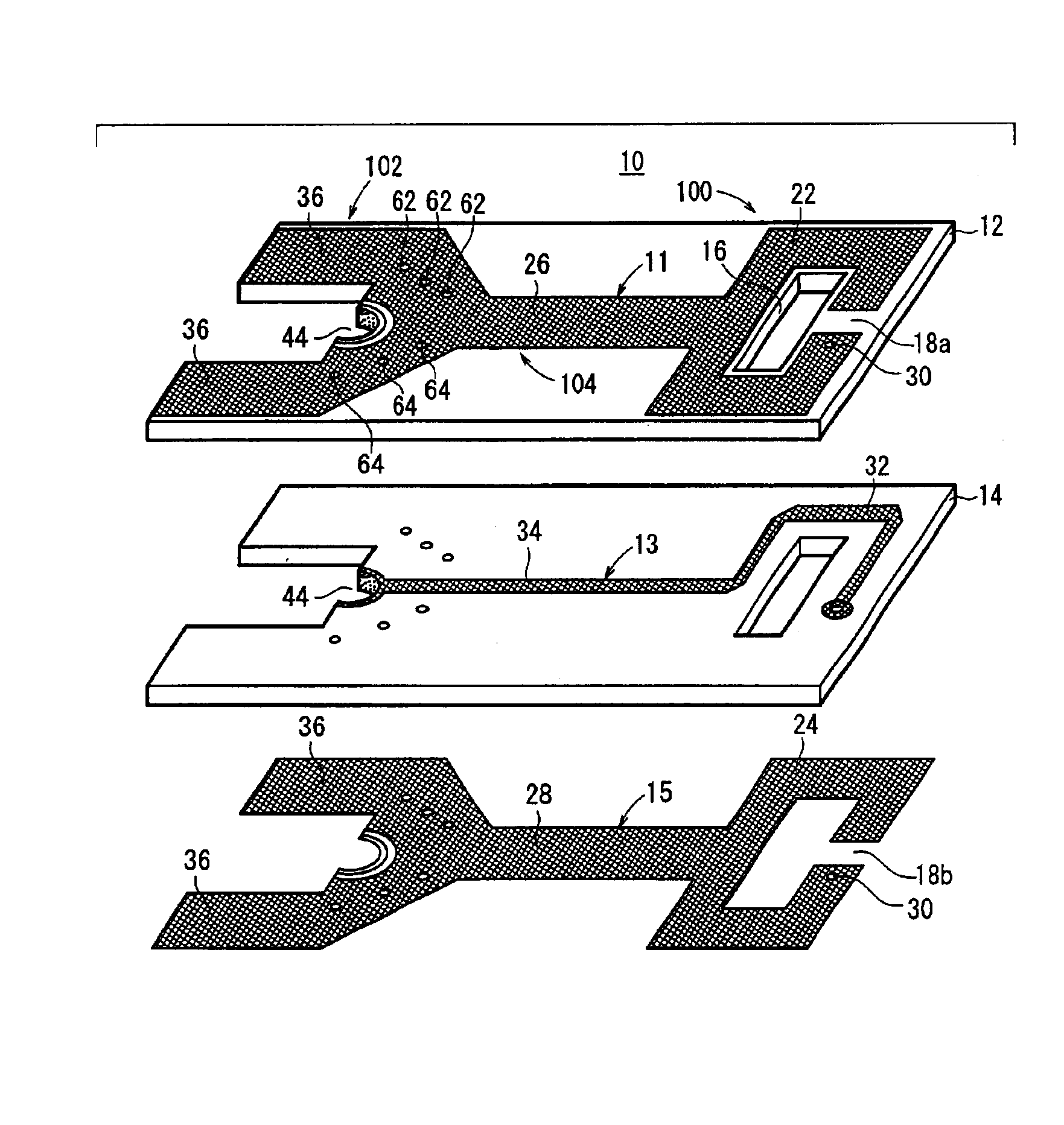
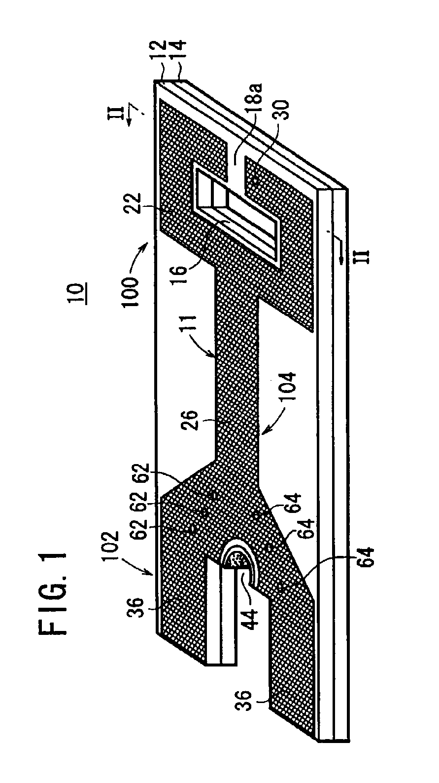
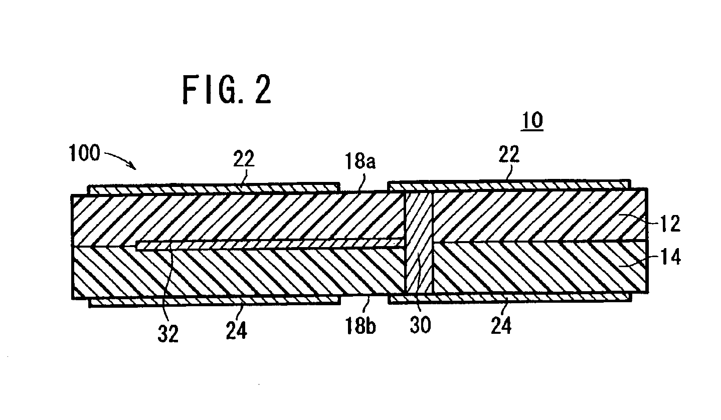
FIG. 1 shows in perspective a magnetic sensor 10 according to the present invention. FIG. 2 shows the magnetic sensor 10 in a cross section taken along line II—II of FIG. 1. FIG. 3 shows the magnetic sensor 10 in exploded perspective. FIG. 4 shows conductor patterns of the magnetic sensor 10 in fragmentary perspective.

As shown in FIG. 1, the magnetic sensor 10 basically comprises a shielded loop coil 100 which functions as a sensor for detecting a magnetic field strength, a high-frequency connection part 102 for connection to a coaxial line or the like to be described later on, and an output lead 104 connecting the shielded loop coil 100 and the high-frequency connection part 102 to each other.

As shown in FIGS. 1 through 4, the magnetic sensor 10 is constructed as a shielded loop coil type magnetic sensor having a triplate stripline structure which employs a five-layer printed circuit board. The five-layer printed circuit board comprises three conductor layers including a first laye...

eighth embodiment

FIG. 21 shows in block form a permeameter 200 according to the present invention.

The permeameter 200 is an apparatus for measuring a complex permeability of a magnetic specimen 202 such as a magnetic thin film material or the like.

The permeameter 200 comprises a side-opened TEM cell 204, details of which will be described later on, functioning as a uniform high-frequency electromagnetic field generating device which receives a magnetic specimen 202 inserted horizontally therein, and a solenoid coil 205 for holding the side-opened TEM cell 204 with the magnetic specimen 202 held therein and applying a DC saturated magnetic field and an unsaturated magnetic field to the magnetic specimen 202. For measuring a permeability of the magnetic specimen 202, the solenoid coil 205 is displaced to the left until the side-opened TEM cell 204 is positioned centrally in the solenoid coil 205.

The solenoid coil 205 is supplied with a predetermined current from a DC power supply 210 which is controll...

ninth embodiment

FIG. 24 shows in perspective a unitary type side-opened TEM cell 204 according to the present invention, the unitary type side-opened TEM cell 204 being machined from stock.


PUM


Abstract

A magnetic sensor has a monotonic response to high-frequency magnetic strengths in a frequency range up to superhigh frequencies. The magnetic sensor includes a shielded loop coil having a triplate stripline structure. The shielded loop coil has one-turn looped ground patterns formed respectively in a first layer and a fifth layer and connected parallel to each other by a via, and has an inductance L. The one-turn looped ground patterns have end electrodes facing each other across gaps, one of the end electrodes including the via, providing a combined capacitor operable at high frequencies and having a capacitance C. The product L×C of the inductance L and the capacitance C is 2.5×10⁻²⁰ or less and the maximum outer circumference length of the one-turn looped ground lines is 50 [mm] or less.

Description

BACKGROUND OF THE INVENTION1. Field of the InventionThe present invention relates to a magnetic sensor which serves as a magnetic field pick-up coil having a monotonic response to magnetic field strength over a wide frequency range from low to superhigh frequencies, a side-opened TEM (Transverse ElectroMagnetic) cell suitable for use in an apparatus for generating a spatially uniform and directional high-frequency electromagnetic field, and a permeameter using such a magnetic sensor and a side-opened TEM cell.2. Description of the Related ArtThe recent rapid advances in IT (Information Technology) accelerate the development of high-speed information and communication instruments as an infrastructural basis for IT. Many developed information and communication instruments have an ability to process signals in frequency ranges up to a GHz frequency range. These high-speed information and communication instruments incorporate many kinds of high-frequency electromagnetic devices includin...

Claims


Application Information

Patent Timeline
Patent Type & Authority Patents(United States)
IPC IPC(8): G01R29/08H01Q7/00G01R33/02G01R33/12
CPCH01Q7/00G01R29/0878
Inventor MIYAZAWA, YASUNORIKAMINISHI, KATSUJIYAMAGUCHI, MASAHIROARAI, KENICHI
Owner RYOWA DENSHI
Why Eureka
Try Eureka