Liquid crystal display apparatus and reduction of electromagnetic interference

Inactive Publication Date: 2005-02-15
SHARP KK
View PDF2 Cites 18 Cited by
  • Summary
  • Abstract
  • Description
  • Claims
  • Application Information

AI Technical Summary

Benefits of technology

It is a general object of the present invention to provide a liquid crystal display apparatus with a lowered EMI level and improved view angle properties, and a production method thereof, which substantially obviates one or more of the problems caused by the limitations and disadvantages of the related art.
According to the liquid crystal display apparatus, the clock signal for transmitting the image data can be stopped temporarily, or the frequency of the clock signal can be reduced.

Problems solved by technology

Therefore, in the conventional liquid crystal display apparatus which has the above configuration, since the clock signal CLK was supplied to each of the data drivers DV1 through DVn with no regard to the data signal DATA, there was a problem of the clock signal CLK causing aggravation of an EMI (electromagnetism interference noise) level and increase in power consumption.
However, overheating and fire hazards of electric apparatuses by harmonics in a low frequency domain and noise interference to TV sets and the like in a high frequency domain have been caused.
Electromagnetic obstacles such as these pose a common problem of every country in the world.
However, when the display of a middle tone, for example, a female picture as shown in FIG. 5, is displayed, a problem arises that the whole picture will become white and the contrast is lost at a lower view angle as shown in FIG.

Method used


Image

  • Liquid crystal display apparatus and reduction of electromagnetic interference
  • Liquid crystal display apparatus and reduction of electromagnetic interference
  • Liquid crystal display apparatus and reduction of electromagnetic interference

Examples


second embodiment

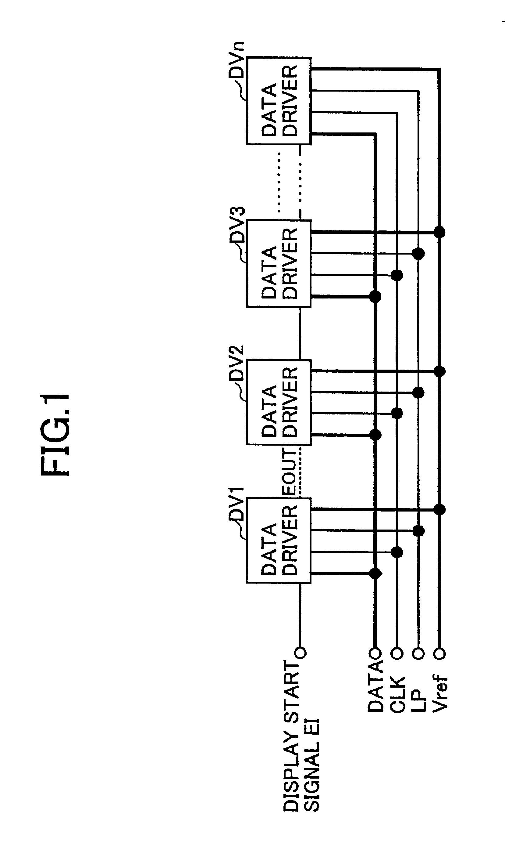
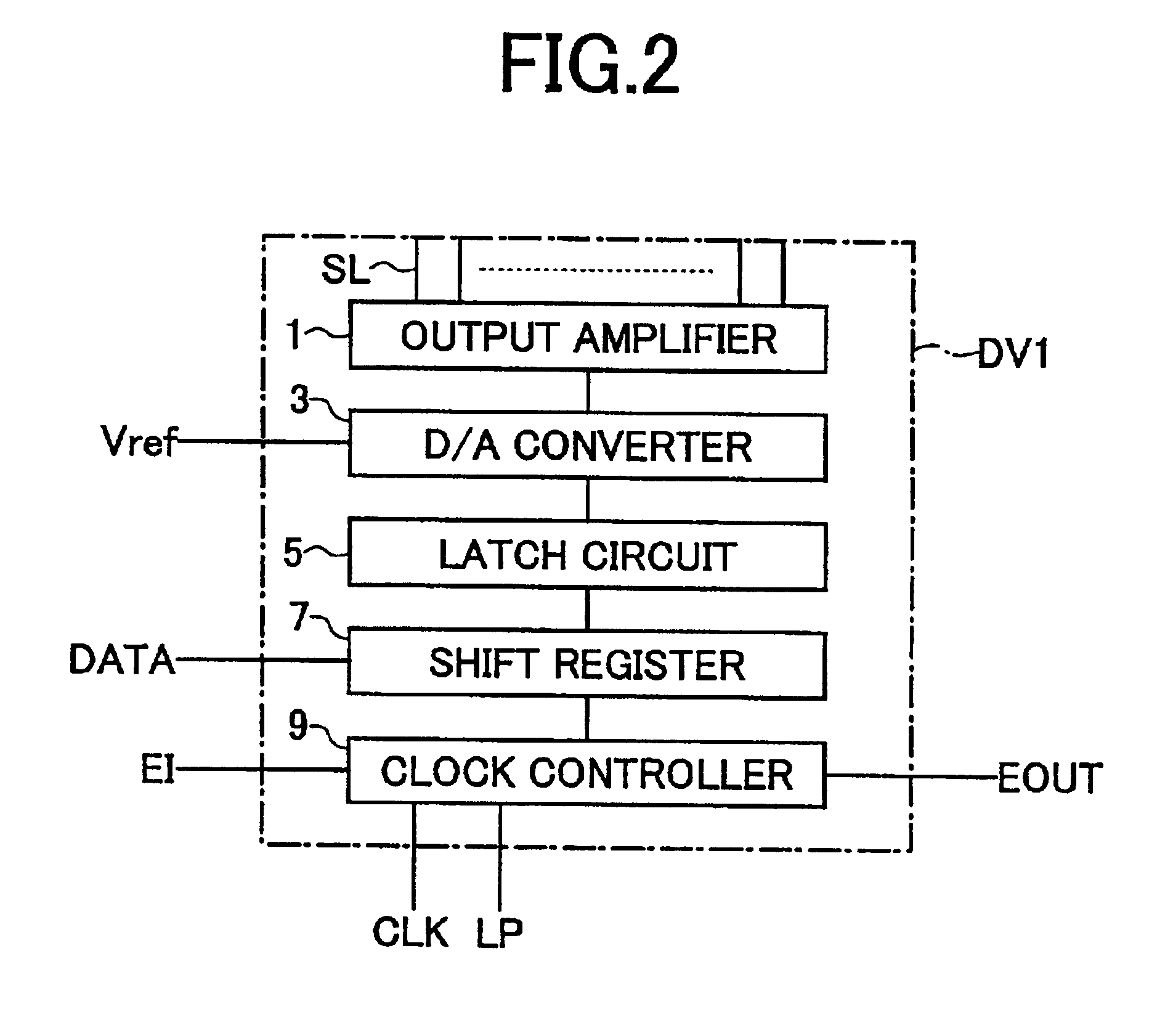
Generally, in the conventional liquid crystal display apparatus, a single edge driving or a double edge driving is adopted. The “single edge driving” is a driving method wherein a data signal is taken in to a data driver using a timing of the level change from one level to the other, e.g., from the low level to the high level with the clock signal of a cycle T as shown in FIG. 18. Further, the “double edge driving” shown in FIG. 19 is a driving method wherein a data signal is taken in to a data driver at a timing of both edges, i.e., logic level changes, with the clock signal of cycle 2T.

In addition, the clock signal (double edge clock signal) of cycle 2T is generated by the circuit that includes a delay flip flop (D-FF) circuit 81 and an inverter 83 as shown in FIG. 20. Here, the input node of the inverter 83 is connected to the output node of the D-FF circuit 81, and the output node of the inverter 83 is connected to the D terminal of the D-FF circuit 81.

In the circuit which has s...

third embodiment

With the data processing speed of systems becoming higher, system driving clock of information machines and equipment is accelerating. Accordingly, circuits are driven by high frequency clocks, causing an increasing necessity of suppressing the noise level of EMI.

Here, although the measures of using a bead and a filter or strengthening a shield structurally have conventionally been taken, in the present condition that drive frequency becomes high, there is a problem that the conventional methods of only eliminating the noise of a clock waveform are insufficient.

Further, although there is the method of moving the frequency of a clock as a solution means, thereby scattering the peak of harmonics, it has a problem that the frequency-shifted clock is asynchronous to the original clock, causing an inability to take synchronization with data.

Then, in the liquid crystal display apparatus of the third embodiment of the present invention, the noise level concentrated on one point is scattere...

fourth embodiment

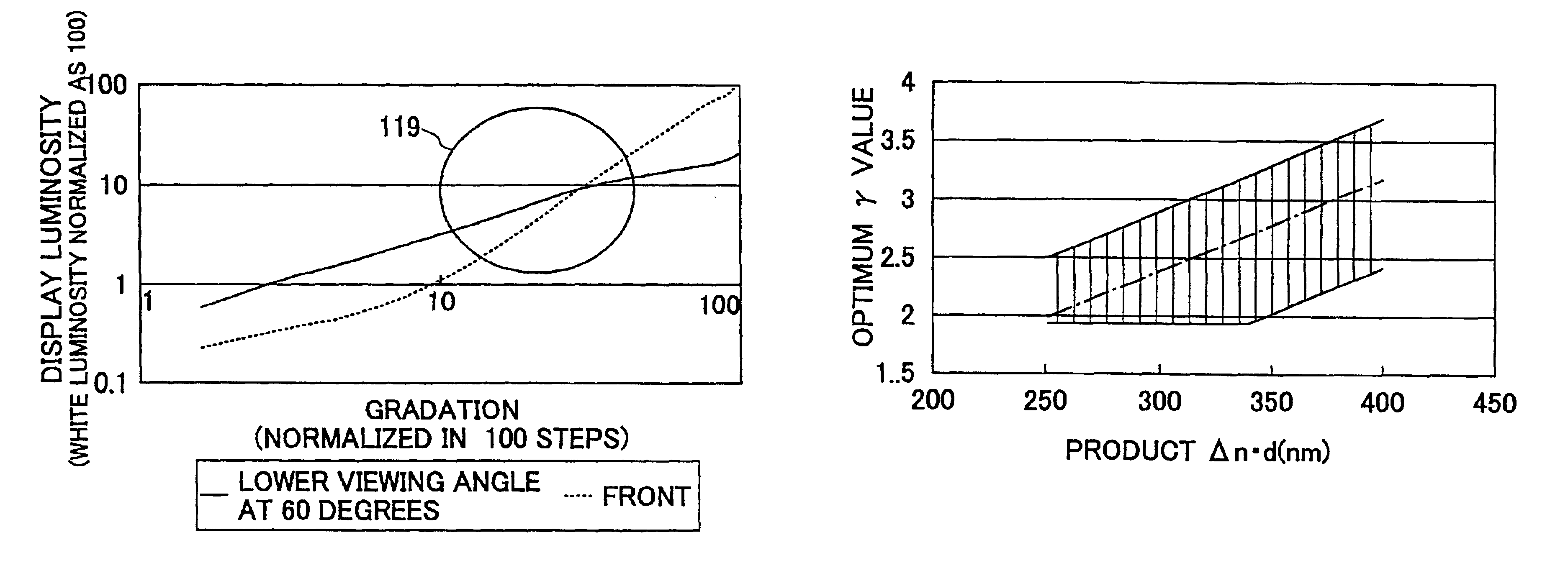
In the display of a middle tone, a problem is that the whole picture becomes white and contrast falls, as shown in FIG. 6. The problem has turned out to be peculiar to an MVA type liquid crystal display apparatus or a liquid crystal panel with divided orientation.

Here, FIG. 32 shows the T-V characteristics (applied voltage dependability of transmissivity) in a lower viewing-angle direction (a liquid crystal molecule responds so that it may incline in the four directions of the upper right, the lower right, the upper left, and the lower left) of an MVA type liquid crystal panel. Although the T-V characteristic surges at the portion 17 corresponding to a middle tone as shown in FIG. 32, it is because the effective birefringence index of the liquid crystal molecule which inclines in the direction of a viewer who observes the liquid crystal panel becomes small.

On the other hand, FIG. 33 is a histogram showing the relation between the gradation and the number of dots within the display a...


PUM


Abstract

A liquid crystal display apparatus includes a liquid crystal display unit, a plurality of data driving units which provide image data to said liquid crystal display unit, and a control unit which enables said plurality of data driving units to take in the image data simultaneously if the image data to be provided to said data driving units are identical.

Description

BACKGROUND OF THE INVENTION1. Field of the InventionThe present invention generally relates to a liquid crystal display apparatus and a manufacturing method thereof.2. Description of the Related ArtFIG. 1 is a block diagram showing the configuration of a data driving unit in a conventional liquid crystal display apparatus. As shown in FIG. 1, the data driving unit in the conventional liquid crystal display apparatus includes data drivers DV1 through DVn. Each of the data drivers DV1 through DVn takes in a data signal DATA according to a supplied display start signal, and supplies an activated display start signal EOUT to a data driver situated at the following stage. In this manner, the data signal DATA is taken in one after another by the data drivers DV1 through DVn that are provided in a parallel arrangement. In addition, as shown in FIG. 1, a clock signal CLK, a latch pulse LP, and a reference voltage Vref are supplied to each of the data drivers DV1 through DVn.FIG. 2 is a bloc...

Claims


Application Information

Patent Timeline
IPC IPC(8): G09G3/36
CPCG09G3/3611G09G3/3685G09G2330/06G09G2320/028G09G2320/0276
Inventor SEKIDO, SATOSHIITO, TAKAENAGATANI, SHINPEIYOSHIDA, HIDEFUMISASABAYASHI, TAKASHIKATAGAWA, KOICHIKISHIDA, KATSUHIKOOSHIRO, MIKIOTANAKA, KATSUNORIMINEMURA, TOSHIMITSUHIRAKI, KATSUYOSHIINOUE, YUICHI
Owner SHARP KK
Why Eureka
Try Eureka