Method of driving a liquid crystal display and driver circuit for driving a liquid crystal display

a liquid crystal display and driver circuit technology, applied in the direction of electric digital data processing, instruments, computing, etc., can solve the problems of deteriorating characteristics of electromagnetic interference of liquid crystal display devices, and increasing the frequency of clock signals. , to achieve the effect of reducing the number of transition time of voltage level bits, and reducing the frequency of clock signals

Active Publication Date: 2007-06-05
NEC LCD TECH CORP
View PDF9 Cites 27 Cited by
  • Summary
  • Abstract
  • Description
  • Claims
  • Application Information

AI Technical Summary

Benefits of technology

[0048]It is a further object of the present invention to provide a novel method of driving a liquid crystal display device, which is capable of reducing a frequency of a clock signal used for transferring image data to a liquid crystal display panel.
[0055]The present invention provides a method of driving a liquid crystal display device having a plurality of bus lines for transmitting image data. The method comprises: branching original image data having an original data rate into branched plural-systems image data comprising plural systems having a converted data rate which is equal to either the original data rate or a half of the original data rate; supplying a source driver circuit with the branched plural-systems image data in synchronization with at least one clock signal having a clock frequency which is a quarter of the original data rate; and allowing the source driver to further branch the branched plural-systems image data into gray-scale voltage signals.

Problems solved by technology

The increase in the frequency of the clock signal would raise a problem with the electromagnetic interference.
Namely, the characteristic in the electromagnetic interference of the liquid crystal display device is deteriorated.
For the reasons described above, it is, however, difficult for the first, second and third conventional methods to respond to the requirement for increase of the image data for each source line without increase in the frequency of the clock signal.
Namely, it would be difficult to satisfy both requirements for the increase of the image data and for avoiding the problem with the electromagnetic interference.
The fourth conventional method is to reduce the frequency of the clock signal without increase in the width or the number of the data bus, for which reason it is difficult to realize a desirable high speed data processing or data transmission.
This means it difficult to realize a desirable improvement in high definition and a desirable increase in size of the display screen of the liquid crystal display panel.
The two system image data make it more difficult to realize the desirable improvement in high definition and the desirable increase in size of the display screen of the liquid crystal display panel.
This increases the total number of the necessary bus lines for transferring the image data, and also increases the times of changing the voltage levels or the bit values of the bus lines.
The electromagnetic interference provides the undesirable influence to operations of peripheral electric, electronic or electron devices.
The provision of any counter-measure tool against the electromagnetic interference increases the cost.
Further, it is difficult to distinguish an electromagnetic noise radiated from the bus line from other electromagnetic noises.
The above conventional methods are also engaged with a further problem with the cross-talk noise which may cause data error.

Method used


Image

  • Method of driving a liquid crystal display and driver circuit for driving a liquid crystal display
  • Method of driving a liquid crystal display and driver circuit for driving a liquid crystal display
  • Method of driving a liquid crystal display and driver circuit for driving a liquid crystal display

Examples


first embodiment

[0139]A first embodiment according to the present invention will be described in detail with reference to the drawings. FIG. 10 is a block diagram illustrative of a novel driver circuit for driving a liquid crystal display in a first embodiment in accordance with the present invention. The liquid crystal display device includes a display panel and a driver circuit having the following circuit configuration.

[0140]The display panel 5A has a two-dimensional array of pixels, each of which includes a pixel electrode and a thin film transistor. The display panel 5A also has a plurality of gate signal lines 51 extending in a row direction and a plurality of source signal lines 52 extending in a column direction. The thin film transistor has a gate electrode connected to the gate signal line 51, a source electrode connected to the source signal line 52 and a drain electrode connected to the pixel electrode.

[0141]The display panel 5A includes a glass substrate, a plurality of source lines ex...

second embodiment

[0190]A second embodiment according to the present invention will be described in detail with reference to the drawings. FIG. 15 is a fragmentary block diagram illustrative of a novel circuit configuration including a timing controller and source drivers in a second embodiment in accordance with the present invention. FIG. 16 is a block diagram illustrative of the timing controller shown in FIG. 15. FIG. 17 is a timing chart illustrative of contents of image data to be supplied in synchronization with first and second clock signals from the timing controller to the source drivers in FIG. 15. FIG. 18 is a diagram illustrative of data structures of A-port data, B-port data, C-port data1 and D-port data shown in FIG. 16.

[0191]In this second embodiment, the image data are converted into four-system image data. The first and second clock signals have a cyclic frequency which is equal to a half of the data rate of the four-system image data. The source drivers incorporate the four-system ...

third embodiment

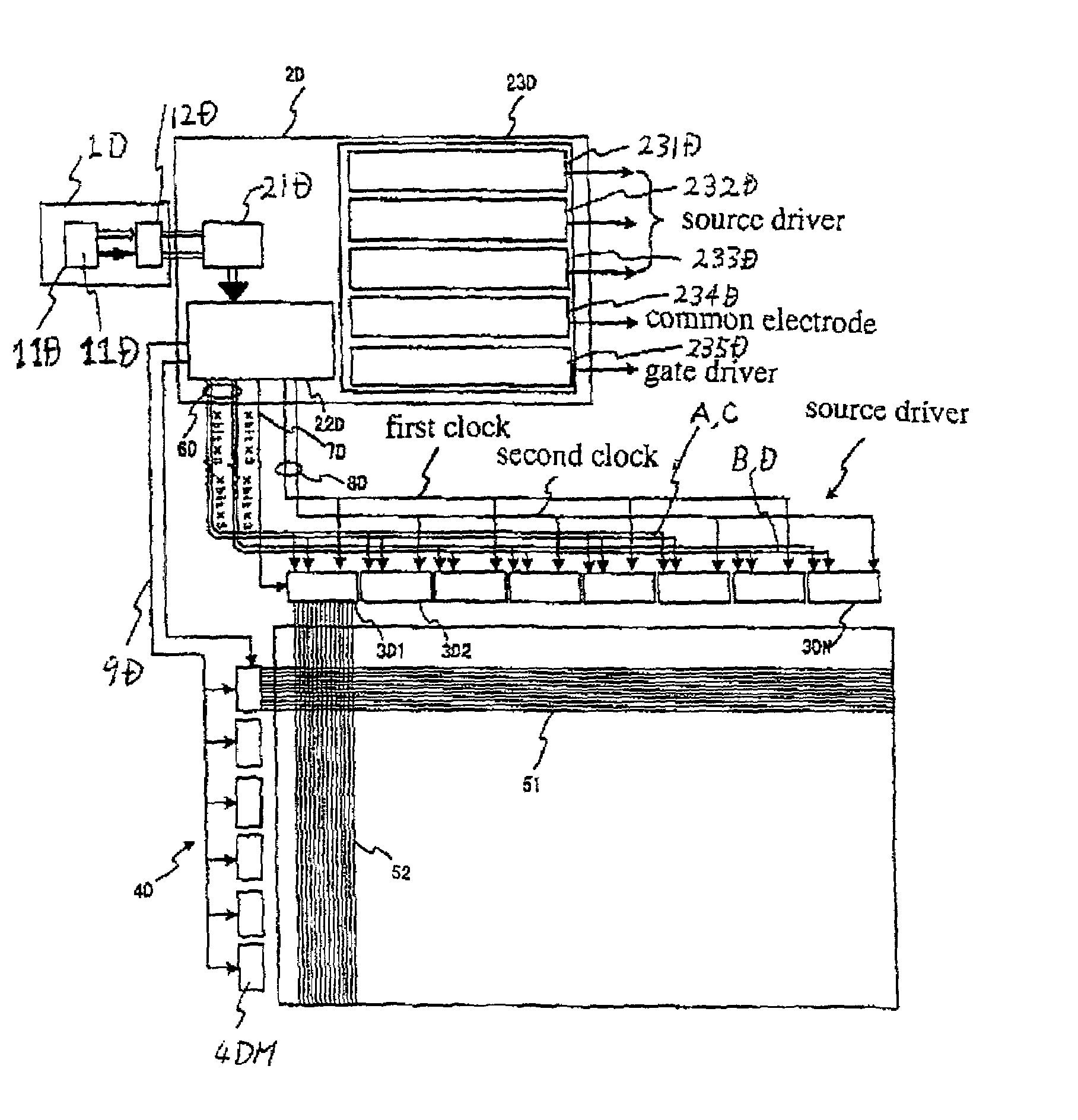
[0209]A third embodiment according to the present invention will be described in detail with reference to the drawings, FIG. 19 is a block diagram illustrative of a novel driver circuit for driving a liquid crystal display in a third embodiment in accordance with the present invention. The liquid crystal display device includes a display panel and a driver circuit having the following circuit configuration. In this third embodiment, the image data are converted into four-system image data. The first and second clock signals have a cyclic frequency which is equal to a half of the data rate of the four-system image data. The source drivers incorporate the four-system image data at the timings of the first and second clock signals.

[0210]The display panel 5C has a two-dimensional array of pixels, each of which includes a pixel electrode and a thin film transistor. The display panel 5C also has a plurality of gate signal lines 51 extending in a row direction and a plurality of source sig...


PUM

PropertyMeasurementUnit
frequencyaaaaaaaaaa
clock frequencyaaaaaaaaaa
gray-scale voltageaaaaaaaaaa

Abstract

A method of driving a liquid crystal display device includes: branching original image data having an original data rate into branched plural-systems image data comprising plural systems having a converted data rate that is equal to either said original data rate or a half of said original data rate; supplying a source driver circuit with said branched plural-systems image data in synchronization with at least one clock signal having a clock frequency that is a quarter of said original data rate; and allowing said source driver circuit to further branch said branched plural-systems image data into gray-scale voltage signals. Circuitry for driving the liquid crystal display device may include: a timing controller; a plurality of data bus lines; and a plurality of source driver circuits for incorporating said image data in synchronization with said at least one clock signal and converting said image data into gray-scale voltage signals.

Description

BACKGROUND OF THE INVENTION[0001]1. Field of the Invention[0002]The present invention relates to a method of driving a liquid crystal display device and a driver circuit for driving a liquid crystal display device, and more particularly to a method of driving a liquid crystal display device and a driver circuit for driving a liquid crystal display device for an ultra-high fine and multi-gray scale display with reducing an electro-magnetic interference.[0003]2. Description of the Related Art[0004]A liquid crystal display has a liquid crystal panel including an array of pixels, each of which includes a pixel electrode and a switching transistor. The switching transistor comprises a thin film transistor. A voltage having a corresponding voltage level to a gray scale is applied through the thin film transistor to the pixel electrode.[0005]It would be important for the liquid crystal display to realize an ultra-high fine display and an increased high speed driving performance of the liqu...

Claims


Application Information

Patent Timeline
Patent Type & Authority Patents(United States)
IPC IPC(8): G09G3/36G09G5/00G02F1/133G09G3/20
CPCG09G3/3611G09G3/3685G09G2310/027G09G2310/0297G09G3/36
Inventor FUJIMOTO, KAZUSHITAKEMOTO, TAKAHIRO
Owner NEC LCD TECH CORP
Why Eureka
Try Eureka