Scanning light source system

a light source and scanning technology, applied in the field of high brightness light sources, can solve the problems of laser sources, too expensive and complex, and to date, and achieve the effect of higher intensity and brightness

Inactive Publication Date: 2005-02-15
INNOVATIONS & OPTICS
View PDF14 Cites 69 Cited by
  • Summary
  • Abstract
  • Description
  • Claims
  • Application Information

AI Technical Summary

Benefits of technology

A method provides a high brightness source of illumination by steps comprising mounting a plurality of modulatable light sources so that they are spatially separated in a prearranged pattern and then exciting the light sources in a predetermined sequence to provide a plurality of light pulses that are separated in space and time and higher in intensity than would otherwise be produced by the sources operating continuously. The outputs of the light sources are scanned to serially receive and redirect them for travel in rapid succession along one or more collection paths to provide a collective output that is comparatively higher in brightness than would otherwise be possible with the light sources operating individually.

Problems solved by technology

Most of these applications require the use of a laser source, which are, to date, expensive and relatively complex.
Therefore, laser sources are not applied to many problems needing a high brightness concentrated light source because they are too expensive and complex.
However, a single LED or single array of LEDs operated continuously (CW) is limited in the brightness that can be obtained when imaged into a spot focus with a given numerical aperture as, for example, that of an optical fiber.
In addition, the optical power out of an LED is limited because of the build up of high levels of damaging heat when operated CW near peak power levels.

Method used


Image

  • Scanning light source system
  • Scanning light source system
  • Scanning light source system

Examples


Embodiment Construction

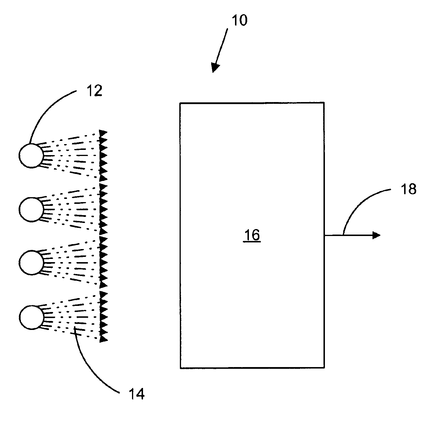
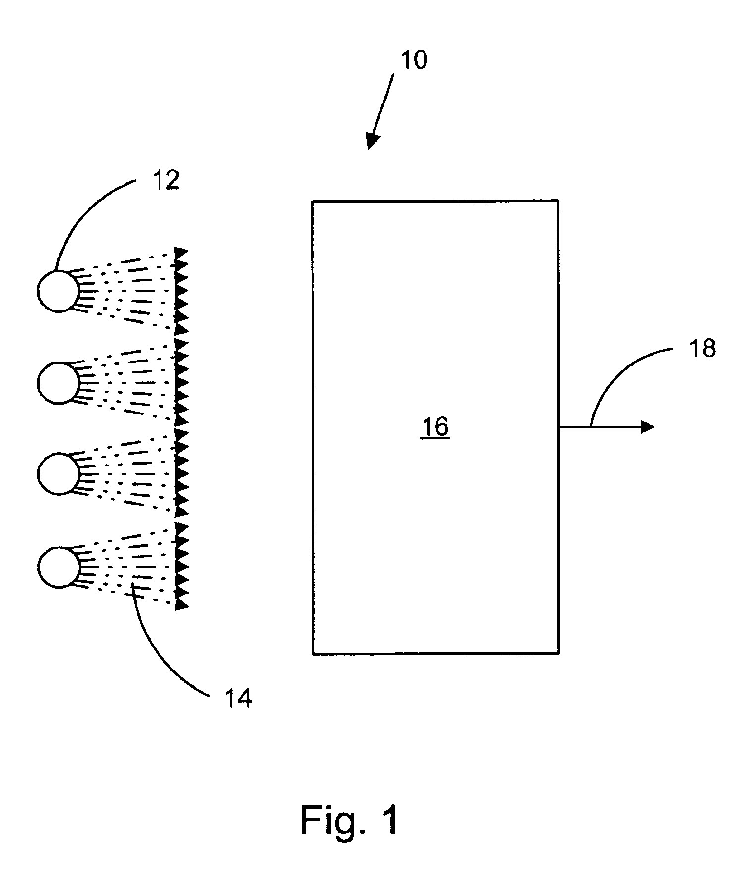
The present invention provides a variety of embodiments for simple, low-cost, high brightness concentrated sources of light that may be used in place of lasers in a range of applications.

Examples of white light applications for the present invention include, but are not limited to, LCD projection systems (Metal Halide or High Pressure Mercury arc lamp replacement), surgical headlights, endoscope illumination, video system illumination, major surgical auxiliary lighting, high brightness industrial illumination, remote light delivery, automotive interior light engine, and / or architectural lighting, etc.

Examples of single color applications for the present invention include, but are not limited to, photodynamic therapy (PDT), adhesive curing systems, and / or medical or dental curing, etc.

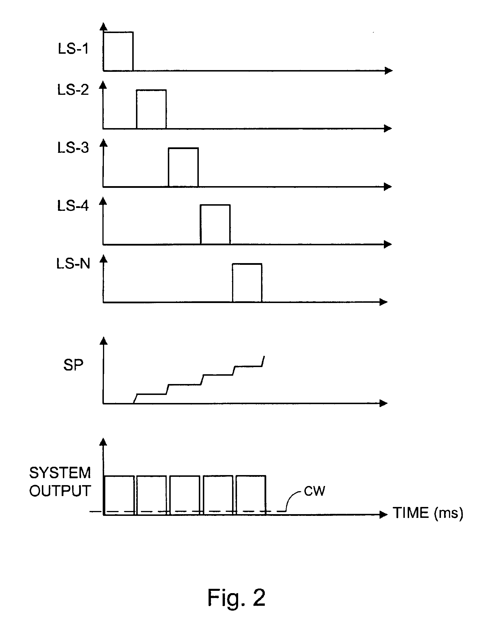
The present invention applies to any source of optical radiation that can be modulated to provide increased peak power with decreased duty cycle including, but not limited to, LED's, laser diodes, xenon...


PUM


Abstract

A scanning light source system combines the outputs from multiple, spatially separated, sequentially pulsed light sources for travel in rapid succession along one or more common delivery paths to provide one or more collective outputs that are comparatively higher than would otherwise be possible with the light sources operating singly.

Description

BACKGROUND OF THE INVENTIONThe present invention generally relates to high brightness light sources and more particularly to apparatus by which the outputs of multiple light sources can be beneficially coupled into a single output whose brightness is greater than that of the individual sources from which it is derived.There are many uses for high brightness concentrated sources of light. Most of these applications require the use of a laser source, which are, to date, expensive and relatively complex. Therefore, laser sources are not applied to many problems needing a high brightness concentrated light source because they are too expensive and complex.Light emitting diodes (LEDs) represent another possible source for achieving high brightness. However, a single LED or single array of LEDs operated continuously (CW) is limited in the brightness that can be obtained when imaged into a spot focus with a given numerical aperture as, for example, that of an optical fiber. In addition, th...

Claims


Application Information

Patent Timeline
Patent Type & Authority Patents(United States)
IPC IPC(8): G02B26/10H01L33/00F21Y101/02F21S8/04H01L33/58H01L33/60H01S5/062
CPCG02B26/10Y10S362/80H01L33/60H01L33/58
Inventor BRUKILACCHIO, THOMAS J.HOUSEHOLDER, JOHN R.HOPKINS, PATRICK W.
Owner INNOVATIONS & OPTICS
Why Eureka
Try Eureka