Color management system

Inactive Publication Date: 2005-02-22
JDS UNIPHASE CORP
View PDF49 Cites 53 Cited by
  • Summary
  • Abstract
  • Description
  • Claims
  • Application Information

AI Technical Summary

Benefits of technology

Accordingly, the use of closely-coupled analyzers positioned to receive light beams directly from associated image assimilators enables the color management system to effectively eliminate a substantial portion of noise imparted on the light beam by each of the image assimilators and to produce output beams having superior contrast relative to the prior a

Problems solved by technology

Unfortunately, currently existing color management systems are capable of achieving increased contrast at practical levels of illuminating flux only by employing highly specialized materials, resulting in unreasonable increases in cost.
Prior art color management systems have thus far not sufficiently proven to be able to produce high contrast images at low cost without compromising their ability to maintain reasonable quantities of illuminating flux or to be packaged efficiently.
This is due, in part, to image noise caused by optical characteristics that are inherent in all real optical elements.
This is also due to the inability of currently existing color management systems to effectively separate and remove such noise from the light beam before it is projected to a display.
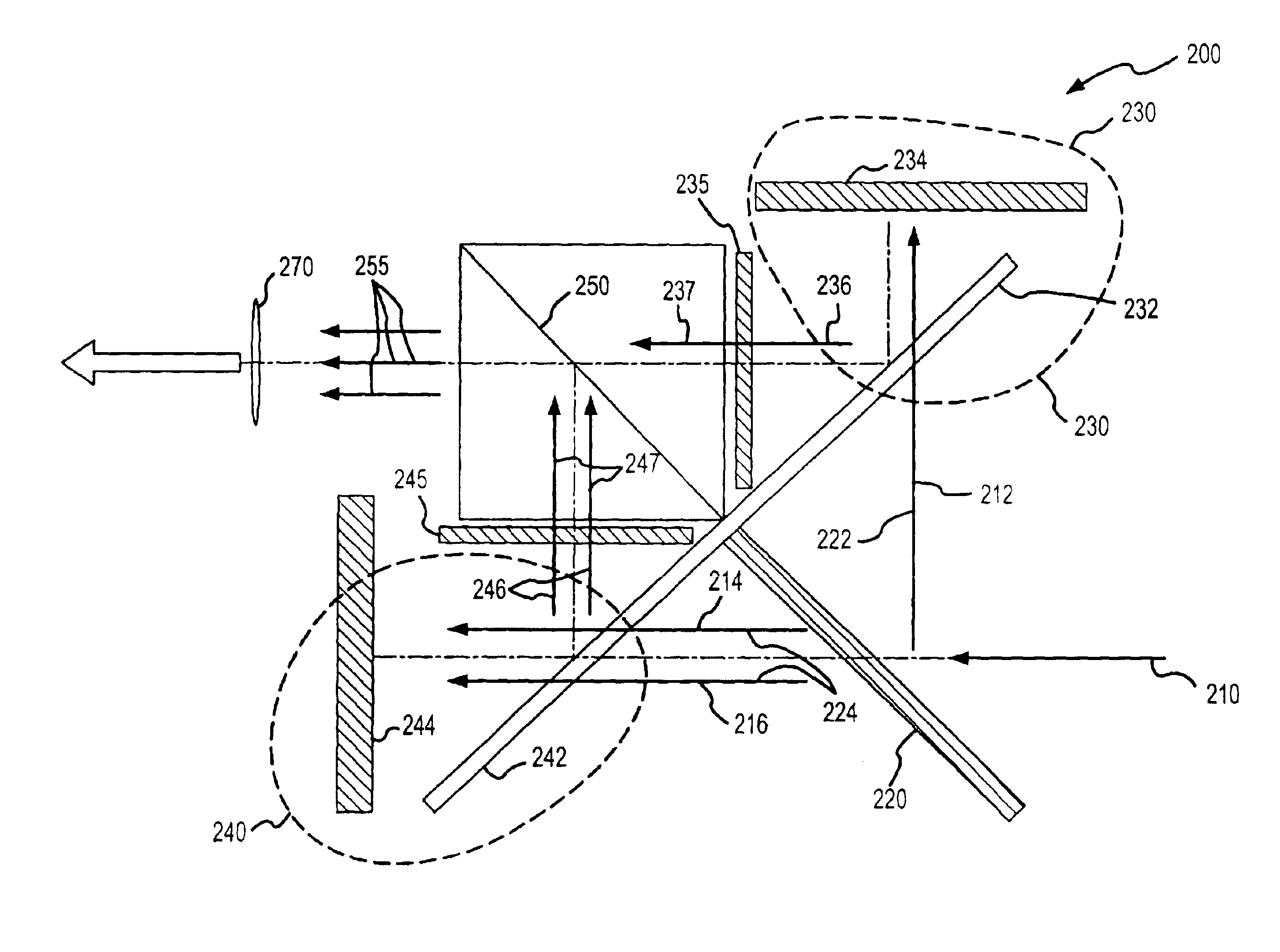
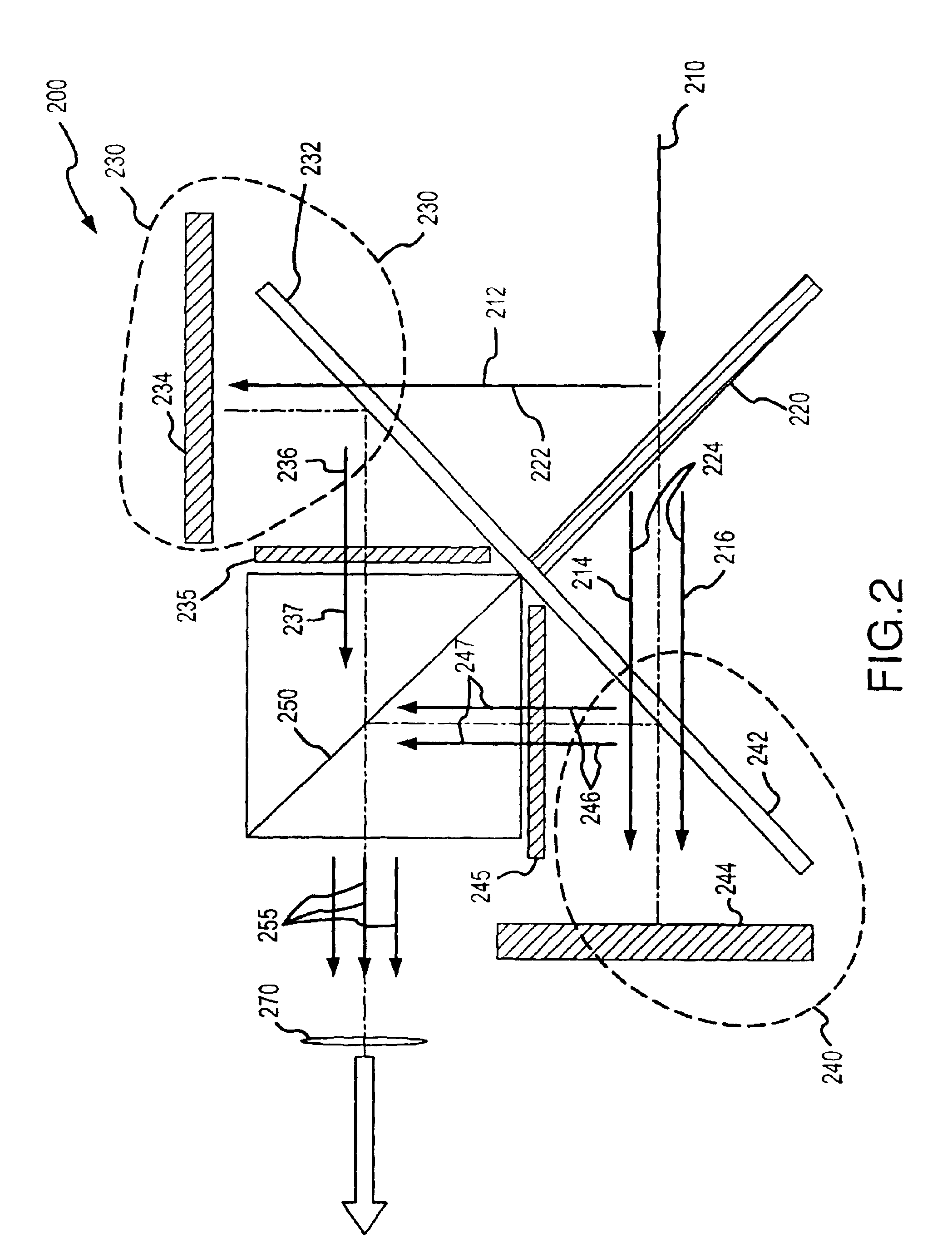
“Cube type” polarizing beamsplitters are inherently susceptible to thermal gradients that typically arise at high flux levels, often causing stress birefringence which results in depolarization of the light and a loss of contrast.
As a result, where high contrast images are desired, it has been necessary to use costly high-index, low-birefringence glass.
Although this solution has proven effective to reduce birefringence at low levels of flux, it is expensive and exhibits reduced effectiveness at eliminating thermally induced birefringence at high flux levels (e.g., greater than approximately 500 lumens).
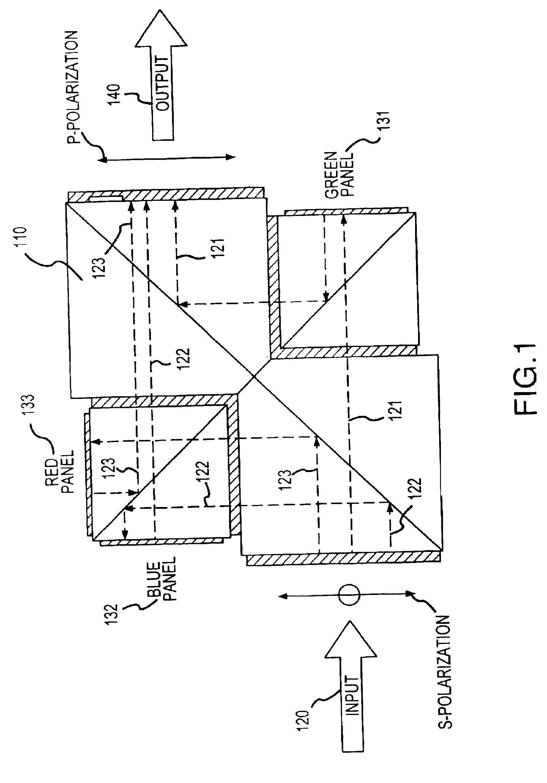
It should be noted that at high levels of light flux, cubic polarizing beamsplitter 110 typically becomes ther

Method used


Image

  • Color management system
  • Color management system
  • Color management system

Examples


Embodiment Construction

The present invention may be described herein in terms of various functional elements and / or various processing steps. It should be appreciated that such functional elements may be realized by any number of software, hardware, electrical, optical and / or structural elements configured to perform the specified functions. For example, the present invention may employ various optical and / or digital electrical elements, whose values may be suitably configured for various intended purposes. In addition, the present invention may be practiced in any optical application. However, for purposes of illustration only, exemplary embodiments of the present invention will be described herein in connection with projection displays. Further, it should be noted that while various elements may be suitably coupled or connected to other elements within exemplary optical systems, such connections and couplings can be realized by direct connection between elements, or by connection through other elements ...


PUM


Abstract

A color management system for use with projection displays includes, for example, two or more analyzers positioned to receive light beams as they are emitted from the panels of a color management system. The analyzers are positioned to receive the light beams directly from the image assimilators before the light has passed through another optical element such as a light combiner. The analyzers are configured for producing filtered light outputs with improved contrast relative to the incoming light beams. By positioning the analyzers to receive the light beams directly from the image assimilators, i.e., prior to passage through other optical elements, the analyzers are able to remove substantially all of the noise before it has become indistinguishable, on the basis of polarization, from the light that comprises the desirable image. Accordingly, this embodiment produces images having dramatically improved levels of contrast relative to prior art systems.

Description

FIELD OF INVENTIONThe present invention relates generally to color management systems for projection displays, and more specifically to systems and methods for separating input illumination into separate color channels, superimposing spatial information on each of the separate channels, eliminating unwanted noise, and recombining the separate color channels to facilitate projection of a high-contrast, full color image.BACKGROUND OF THE INVENTIONIn conjunction with a projection display, it is desirable to employ a color management system, and it is further desirable that such color management system facilitate the production of a high contrast image while accommodating a relatively high level of illuminating flux and providing for efficient packaging. Unfortunately, currently existing color management systems are capable of achieving increased contrast at practical levels of illuminating flux only by employing highly specialized materials, resulting in unreasonable increases in cost....

Claims


Application Information

Patent Timeline
IPC IPC(8): H04N9/31G03B21/00G02B5/30
CPCH04N9/3105H04N9/3197H04N9/3167
Inventor PENTICO, CLARKNEWELL, MICHAEL
Owner JDS UNIPHASE CORP
Why Eureka
Try Eureka