Controlled patterning and growth of single wall and multi-wall carbon nanotubes

a carbon nanotube and patterning technology, applied in the direction of carbonsing rags, chemistry apparatus and processes, fibre chemical treatment, etc., can solve the problems of difficult or impossible patterning of finely detailed arrays of such structures, difficult to discriminate between, and control the growth,

Inactive Publication Date: 2005-02-22
NASA +1
View PDF7 Cites 230 Cited by
  • Summary
  • Abstract
  • Description
  • Claims
  • Application Information

AI Technical Summary

Benefits of technology

These needs are met by the invention, which provides (1) separate procedures for generating and controlling patterns of growth of an array of SWNTs, an array of MWNTs and/or an array of NFs, with a carbon nanotube length that depends upon the structure involved. In one embodiment, an array of SWNTs is grown by providing a substrate coated with an optional first thickness (preferably at least 1-10 nm) of a metal underlayer (e.g., Al or Ir or a mixture thereof) and with a second thickness (preferably at least 0.1-5 nm) of one or more active catalysts (e.g., Fe, Co, Ni and/or Mo, or a mixture thereof) and passing a selected heated hydrocarbon gas (e.g., CH4, C2H4, and/or C2H2) intermediate species (CmHn) over the coated substrate to successively strip the H atoms and deposit the carbon particles on the catalyst. Opt...

Problems solved by technology

However, it is not straightforward to discriminate between, and control the growth of, a single wall nanotube (“SWNT”), a multi-wall nanotube (“MWNT”) and/or a nanofiber (“NF”).
So...

Method used


Image

  • Controlled patterning and growth of single wall and multi-wall carbon nanotubes
  • Controlled patterning and growth of single wall and multi-wall carbon nanotubes
  • Controlled patterning and growth of single wall and multi-wall carbon nanotubes

Examples


Embodiment Construction

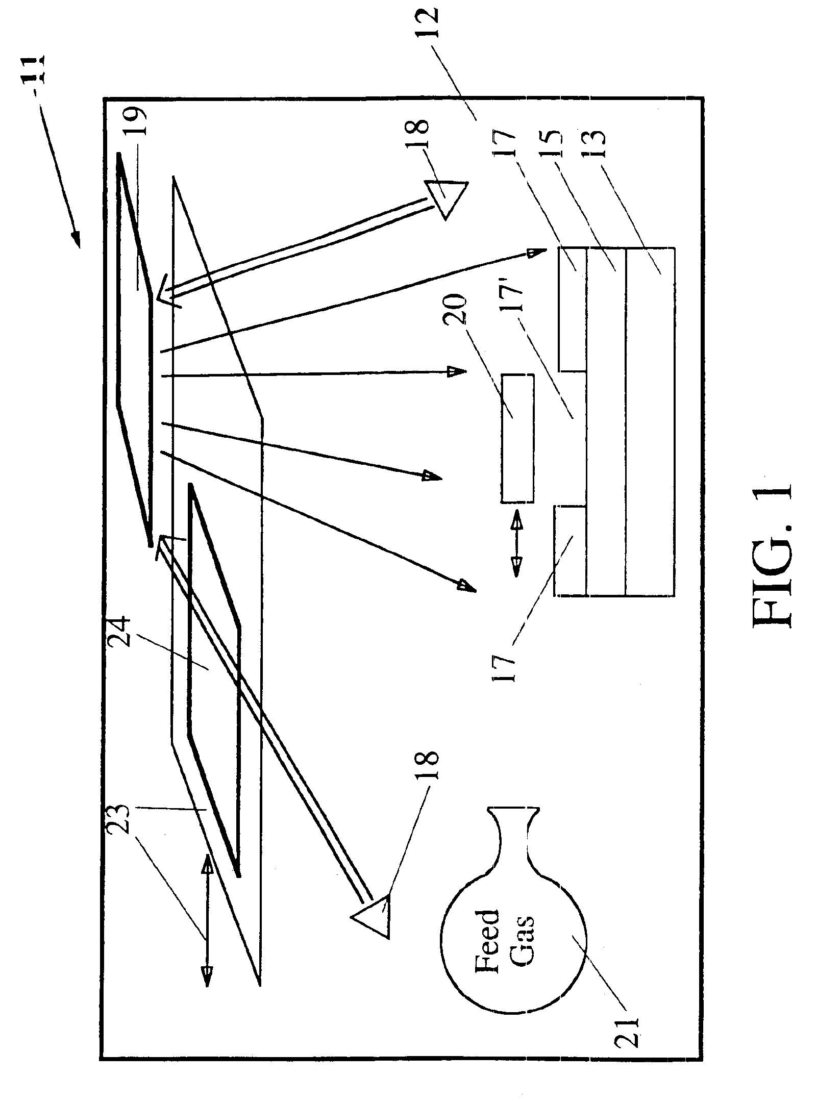
FIG. 1 illustrates a system 11 for generating and controlling patterned growth of an array of SWNTs. A substrate 13 located in a chamber 12 is coated with a first layer 15 (optional) of a selected first metal, preferably Al and / or Ir, having a thickness of at least 1-10 nm (for Al) or 5-20 nm (for Ir). A thicker first layer can be used but does not produce any significant changes in the array thus produced. Optionally, the first layer 15 has a multi-layer structure, including a first sub-layer 15A of a metal or alloy, such as Pt, Pd, Cr, Mo, Ti and / or W, that has selected electrical conductivity properties, and a second sub-layer 15B, preferably Al (thickness ≧1-10 nm) or Ir (thickness ≧5-20 nm), that provides a structure for a catalyst layer 17. Use of a second sub-layer 15B also allows growth of SWNTs, MWNTs and NFs on a (coated) substrate that is not compatible with the catalyst. An example is use of highly oriented pyrolytic graphite (HOPG) or amorphous carbon on the substrate. ...


PUM


Abstract

Method and system for producing a selected pattern or array of at least one of a single wall nanotube and/or a multi-wall nanotube containing primarily carbon. A substrate is coated with a first layer (optional) of a first selected metal (e.g., Al and/or Ir) and with a second layer of a catalyst (e.g., Fe, Co, Ni and/or Mo), having selected first and second layer thicknesses provided by ion sputtering, arc discharge, laser ablation, evaporation or CVD. The first layer and/or the second layer may be formed in a desired non-uniform pattern, using a mask with suitable aperture(s), to promote growth of carbon nanotubes in a corresponding pattern. A selected heated feed gas (primarily CH4 or C2Hn with n=2 and/or 4) is passed over the coated substrate and forms primarily single wall nanotubes or multiple wall nanotubes, depending upon the selected feed gas and its temperature. Nanofibers, as well as single wall and multi-wall nanotubes, are produced using plasma-aided growth from the second (catalyst) layer. An overcoating of a selected metal or alloy can be deposited, over the second layer, to provide a coating for the carbon nanotubes grown in this manner.

Description

FIELD OF THE INVENTIONThis invention relates to controlled deposition of catalysts for growth of carbon nanotubes.BACKGROUND OF THE INVENTIONIn 1991, S. Iijima (Nature, vol. 354 pp. 56-58) reported growth of multi-wall coaxial nanotubes, containing 2-50 layers with radial separations of about 0.34 nm, using an arc discharge evaporation method similar to that used for Fullerene synthesis. The nanotubes originally observed by Iijima were formed on the negative voltage end of a carbon electrode and were plentiful in some regions and sparse in other regions. Since that time, other workers have developed other discharge means for controlled deposition of graphitic carbon. However, it is not straightforward to discriminate between, and control the growth of, a single wall nanotube (“SWNT”), a multi-wall nanotube (“MWNT”) and / or a nanofiber (“NF”).The SWNTs, MWNTs and NFs potentially have many applications that rely upon the large mechanical strength and / or large electrical conductivity as...

Claims


Application Information

Patent Timeline
IPC IPC(8): D01F9/127D01F9/12C01B31/02
CPCB82Y30/00B82Y40/00C01B31/0233D01F9/1271D01F9/1272D01F9/1273D01F9/1275C01B2202/02C01B2202/06Y10S977/843Y10S977/75C01B2202/36C01B32/162
Inventor DELZEIT, LANCE D.
Owner NASA
Why Eureka
Try Eureka