Low-profile transformer and method of manufacturing the transformer
a transformer and low-profile technology, applied in the direction of transformers, magnets, continuously variable inductances/transformers, etc., can solve the problems of increasing power consumption, affecting the operability of the mounting of the magnetic core, and the relative position between the coil and the insulating paper b>3/b> becoming unstabl
- Summary
- Abstract
- Description
- Claims
- Application Information
AI Technical Summary
Benefits of technology
Problems solved by technology
Method used
Image

Examples
first exemplary embodiment
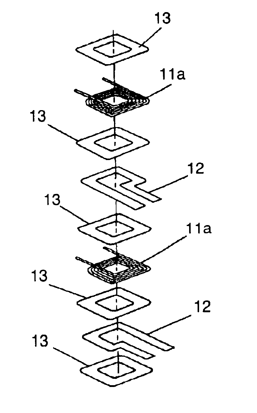
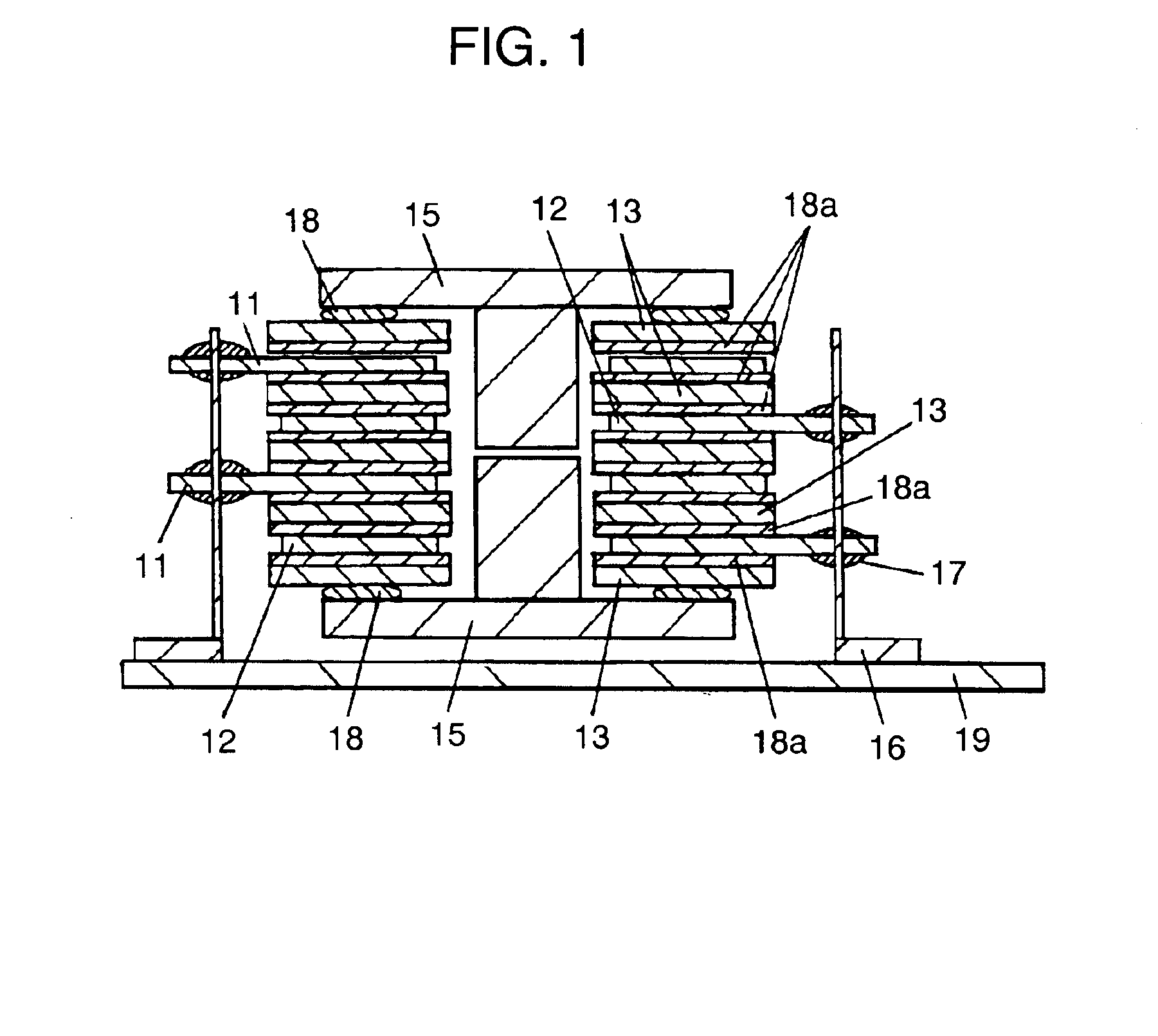
FIG. 1 is a sectional view showing a laminated structure of a thin transformer of a first exemplary embodiment of the invention. As shown in FIG. 1, a coil of a non-wirewound type is produced from a thin copper sheet by such a method as punching or etching. Two each of such coils are prepared and they are used as primary coil 11 and secondary coil 12. Then, insulating paper 13 provided with pressure sensitive adhesive 18a attached to both sides thereof is stamped into a predetermined shape. Insulating paper 13 provided with pressure sensitive adhesive 18a may be a commercially-available pressure sensitive adhesive tape.
Otherwise, insulating paper 13 may be applied with either pressure sensitive adhesive 18a or adhesive 18 and may thereafter be used. It is preferred that insulating paper 13 be a heat-resistant polyimide film (PI). Other than PI, any of insulating thin film materials may be used for insulating paper 13. Then, as shown in FIG. 1, insulating paper 13 with pressure sensi...
second exemplary embodiment
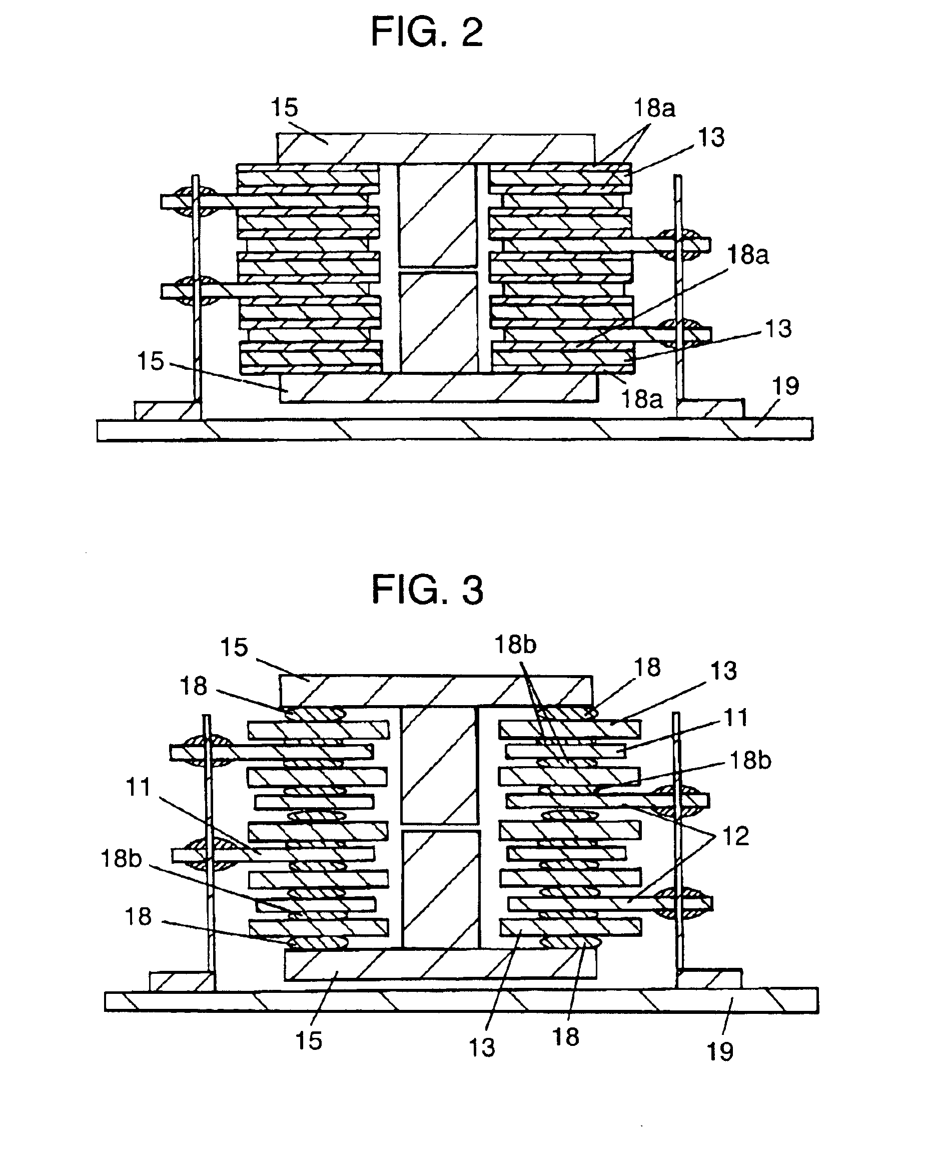
FIG. 2 is a sectional view showing a laminated structure of a thin transformer of a second exemplary embodiment of the invention. The structure is basically the same as that in the first exemplary embodiment. It greatly differs therefrom in that pressure sensitive adhesive 18a is disposed on both sides of insulating paper 13 on the bottommost layer and topmost layer. By disposing pressure sensitive adhesive 18a on both sides of at least one of insulating papers 13 placed at the bottommost layer and topmost layer, the need for the step for bonding the coil and the core together can be eliminated.
third exemplary embodiment
A third exemplary embodiment of the invention will be described with reference to FIG. 3 and FIG. 4. FIG. 3 is a sectional view showing a laminated structure of a thin transformer of a third exemplary embodiment of the invention. FIG. 4 is a sectional view showing an adhesive used in the third embodiment of the invention. Basic structure shown in FIG. 3 and FIG. 4 is the same as that shown in FIG. 1. It greatly differs from that in the point that adhesive 18b is applied not to the entire surface of insulating paper 13 but to part of the surface. In the manufacturing process, adhesive 18b is applied to part of insulating paper 13, not to the entire surface facing the coil. Material of adhesive 18b used on the bottommost layer and the topmost layer is the same as that of adhesive 18b used between coil layers. Since the same adhesive coating machine can be shared, investment can be decreased. Further, the amount of the adhesive used can be reduced. Since the need for applying adhesive ...
PUM
| Property | Measurement | Unit |
|---|---|---|
| melting point | aaaaa | aaaaa |
| temperatures | aaaaa | aaaaa |
| pressure sensitive | aaaaa | aaaaa |
Abstract
Description
Claims
Application Information
 - R&D
- Intellectual Property
- Life Sciences
- Materials
- Tech Scout
- Unparalleled Data Quality
- Higher Quality Content
- 60% Fewer Hallucinations
Browse by: Latest US Patents, China's latest patents, Technical Efficacy Thesaurus, Application Domain, Technology Topic, Popular Technical Reports.
© 2025 PatSnap. All rights reserved.Legal|Privacy policy|Modern Slavery Act Transparency Statement|Sitemap|About US| Contact US: help@patsnap.com